
learnsteam
Document register
- Poster1 pagePublished
- Presentation videoYouTubePublished
- Bill of materials42 KBPublished
- Team description paper10 pagesPublished
- Engineering journalNot shared
- Source code112 KB · GitHubPublished
Sharing each document is the team's decision. “Not shared” means this team chose not to publish it, or did not submit one — not that it is missing from the archive.

In their words
Team RM developed an autonomous rescue simulation robot designed to explore unknown
environments, detect victims and hazardous materials, generate maps, and return to the
starting point within the given time limit. The robot uses two motors, three cameras, GPS, a
gyroscope, and a 360-degree LiDAR sensor. LiDAR is used for obstacle detection,
point-cloud generation, and real-time mapping, while GPS and gyroscope data help estimate
the robot’s position and direction. The front, left, and right cameras identify wall tokens,
victims, hazardous signs, and floor types through OpenCV-based image processing.
The main feature of our robot is the integration of multiple sensors with a noise-aware
navigation and mapping system. Instead of relying only on simple obstacle detection, the
robot uses A* pathfinding, navigation preference values, and continuously updated map
layers to select safer routes. Compared with our previous version, the robot was redesigned to
reduce the effects of sensor noise and improve movement stability. These improvements
allowed the robot to explore more consistently, detect important objects more reliably, and
create a more accurate map during the simulation.
Poster
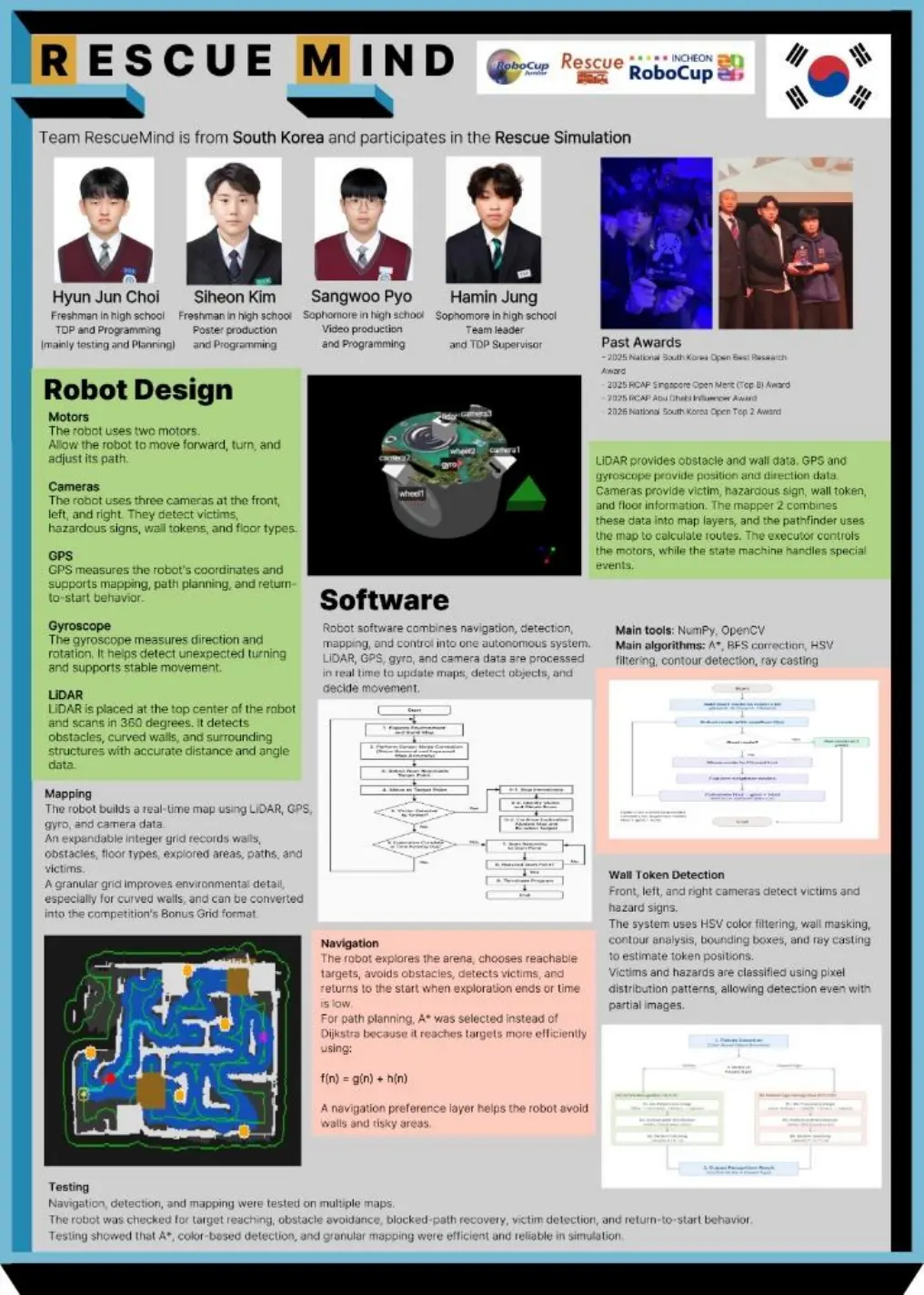
1 page, rendered as images so they load quickly. This document has no text layer — the words in it are part of the image.
Presentation video
Hosted on YouTube. The player loads only when you press play.
Bill of materials
Shown as the original PDF, because this one is smaller that way and its text stays selectable and searchable.
Team description paper
Show the remaining 7 pages
Read the text of this document — 2155 words
ROBOCUPJUNIOR RESCUE SIMULATION 2026
TEAM DESCRIPTION PAPER
Rescue Mind
Abstract
Team RM developed an autonomous rescue simulation robot designed to explore unknown
environments, detect victims and hazardous materials, generate maps, and return to the
starting point within the given time limit. The robot uses two motors, three cameras, GPS, a
gyroscope, and a 360-degree LiDAR sensor. LiDAR is used for obstacle detection,
point-cloud generation, and real-time mapping, while GPS and gyroscope data help estimate
the robot’s position and direction. The front, left, and right cameras identify wall tokens,
victims, hazardous signs, and floor types through OpenCV-based image processing.
The main feature of our robot is the integration of multiple sensors with a noise-aware
navigation and mapping system. Instead of relying only on simple obstacle detection, the
robot uses A* pathfinding, navigation preference values, and continuously updated map
layers to select safer routes. Compared with our previous version, the robot was redesigned to
reduce the effects of sensor noise and improve movement stability. These improvements
allowed the robot to explore more consistently, detect important objects more reliably, and
create a more accurate map during the simulation.
Keywords: Pathfinding, A* Algorithm, Dijkstra’s Algorithm, Wall Token Detection,
OpenCV, Mapping, NumPy, LiDAR, Sensor Noise Reduction
1. Introduction
a. Team
Jung Ha-min worked on coding and the Team Description Paper. He helped organize the
project documentation and explained the robot’s software structure, project goals, and
technical decisions.
Pyo Sang-woo mainly contributed to coding and video production. He supported the
development of navigation and detection functions and helped present the robot’s behavior
through the team video.
Kim Si-heon contributed to coding and poster production. He worked on exploration, path
planning, and detection functions, and designed the poster to summarize the robot’s main
improvements.
Choi Hyun-jun worked on coding and the Team Description Paper. He supported software
testing and helped connect the team’s technical implementation with the overall project plan.
1
2. Project Planning
a. Overall Project Plan
Team RM’s objective was to build a more reliable and efficient robot than the previous
competition version. The robot had to explore the map, detect victims and hazardous signs,
avoid obstacles, record floor types, generate an accurate map, and return to the starting point
before the time limit.
The main constraints were the robot customization budget, limited match time, competition
rules, and sensor noise. Because of these constraints, the team focused on efficient sensor
placement, stable path planning, accurate detection, and noise reduction.
The project was planned in the following order: robot design, software architecture,
navigation, detection, mapping, and testing. This order was chosen because the software
depended on the sensor layout and available sensor data.
Milestone 1: Sensor Configuration and Robot Design
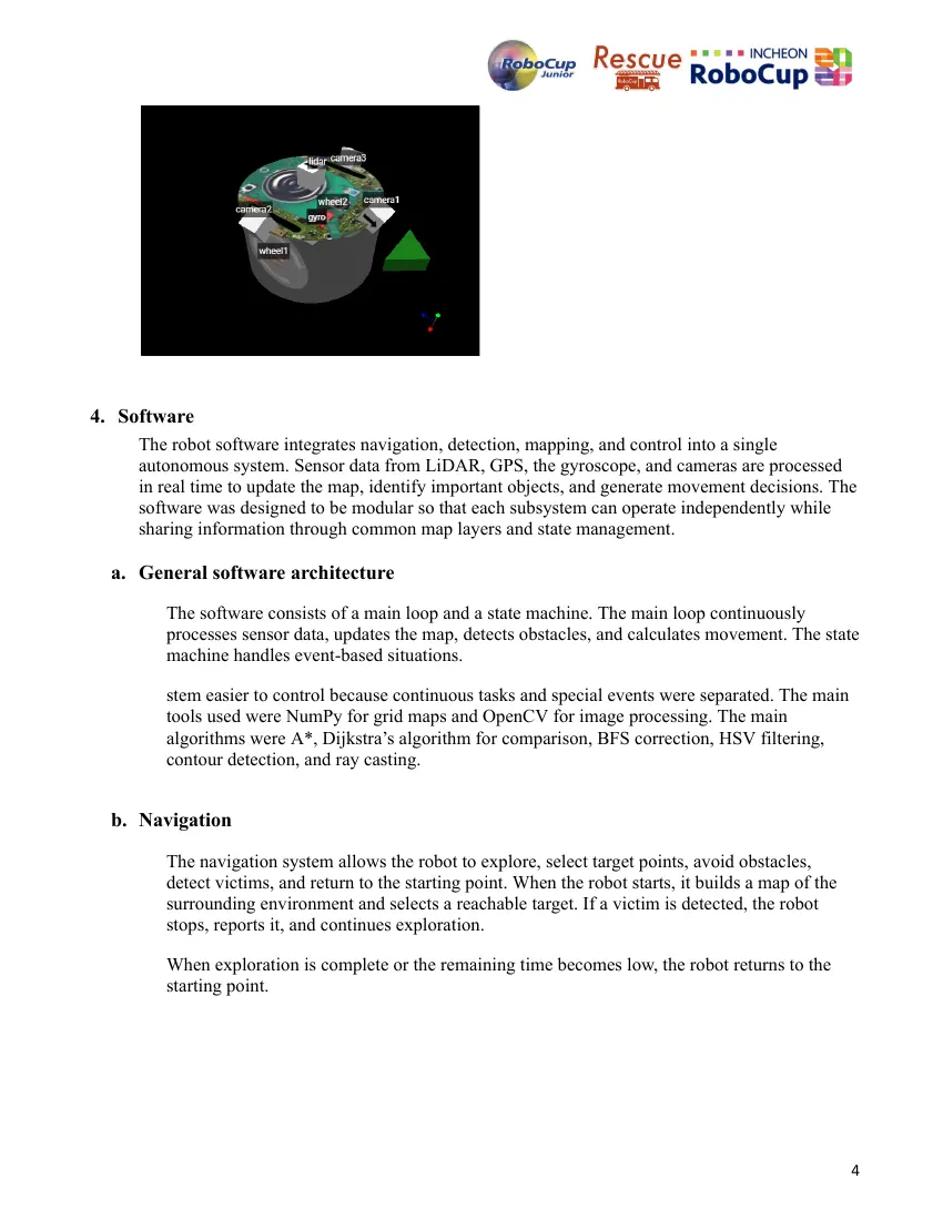
The team redesigned the robot’s sensor layout based on problems from the previous
competition. Three cameras were placed at the front, left, and right sides, while LiDAR was
placed at the top center for 360-degree detection. GPS and the gyroscope were placed near
the center for stable position and direction data.
Milestone 2: Software Architecture
The team divided the software into a main loop and a state machine. The main loop handles
continuous tasks such as navigation, mapping, and obstacle detection. The state machine
handles special situations such as initialization, victim reporting, stuck state, and ending.
Milestone 3: Function Development
The team implemented LiDAR-based obstacle detection, OpenCV-based image processing,
A* pathfinding, and NumPy-based mapping. Based on previous performance, the team
changed from a node-based grid to a granular grid to improve curved-wall recognition and
mapping accuracy.
Milestone 4: Testing and Improvement
The robot was tested on multiple maps. The team checked exploration consistency, victim
detection, obstacle avoidance, mapping accuracy, and return-to-start behavior. Test results
were used to improve navigation stability and reduce the effects of sensor noise.
b. Integration Plan
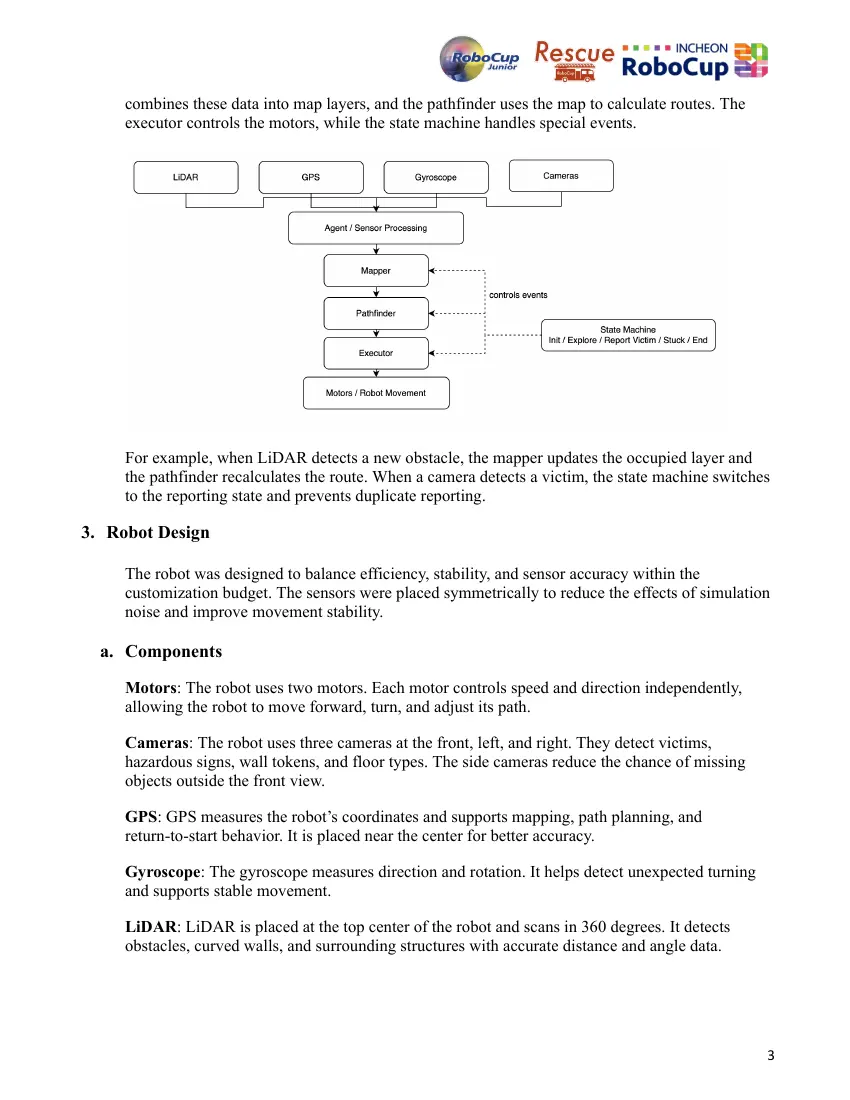
The robot was integrated by connecting the sensor system, mapper, pathfinder, executor, and
state machine. Each component satisfied one of the project requirements.
LiDAR provides obstacle and wall data. GPS and gyroscope provide position and direction data.
Cameras provide victim, hazardous sign, wall token, and floor information. The mapper
2
combines these data into map layers, and the pathfinder uses the map to calculate routes. The
executor controls the motors, while the state machine handles special events.
For example, when LiDAR detects a new obstacle, the mapper updates the occupied layer and
the pathfinder recalculates the route. When a camera detects a victim, the state machine switches
to the reporting state and prevents duplicate reporting.
3. Robot Design
The robot was designed to balance efficiency, stability, and sensor accuracy within the
customization budget. The sensors were placed symmetrically to reduce the effects of simulation
noise and improve movement stability.
a. Components
Motors: The robot uses two motors. Each motor controls speed and direction independently,
allowing the robot to move forward, turn, and adjust its path.
Cameras: The robot uses three cameras at the front, left, and right. They detect victims,
hazardous signs, wall tokens, and floor types. The side cameras reduce the chance of missing
objects outside the front view.
GPS: GPS measures the robot’s coordinates and supports mapping, path planning, and
return-to-start behavior. It is placed near the center for better accuracy.
Gyroscope: The gyroscope measures direction and rotation. It helps detect unexpected turning
and supports stable movement.
LiDAR: LiDAR is placed at the top center of the robot and scans in 360 degrees. It detects
obstacles, curved walls, and surrounding structures with accurate distance and angle data.
3
4. Software
The robot software integrates navigation, detection, mapping, and control into a single
autonomous system. Sensor data from LiDAR, GPS, the gyroscope, and cameras are processed
in real time to update the map, identify important objects, and generate movement decisions. The
software was designed to be modular so that each subsystem can operate independently while
sharing information through common map layers and state management.
a. General software architecture
The software consists of a main loop and a state machine. The main loop continuously
processes sensor data, updates the map, detects obstacles, and calculates movement. The state
machine handles event-based situations.
stem easier to control because continuous tasks and special events were separated. The main
tools used were NumPy for grid maps and OpenCV for image processing. The main
algorithms were A*, Dijkstra’s algorithm for comparison, BFS correction, HSV filtering,
contour detection, and ray casting.
b. Navigation
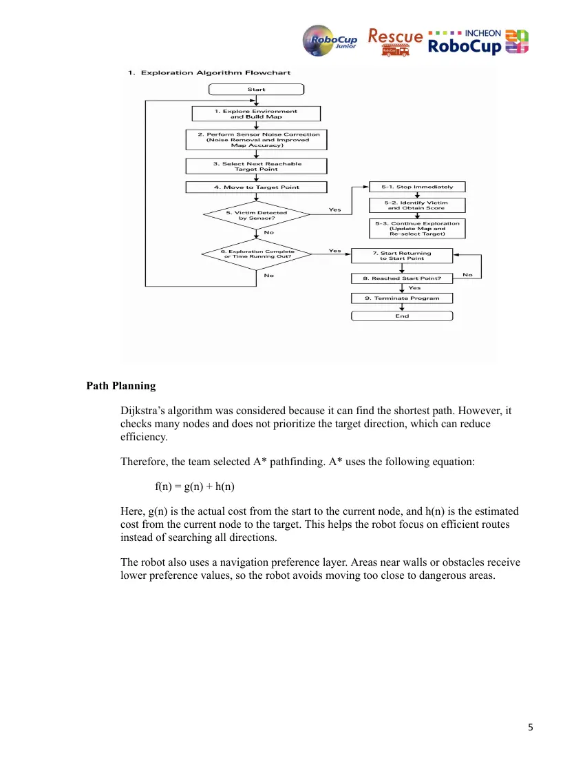
The navigation system allows the robot to explore, select target points, avoid obstacles,
detect victims, and return to the starting point. When the robot starts, it builds a map of the
surrounding environment and selects a reachable target. If a victim is detected, the robot
stops, reports it, and continues exploration.
When exploration is complete or the remaining time becomes low, the robot returns to the
starting point.
4
Path Planning
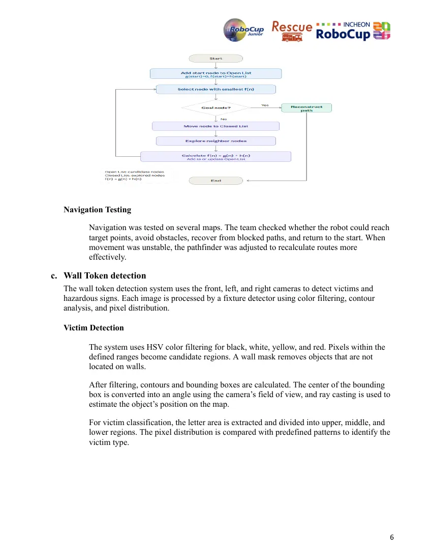
Dijkstra’s algorithm was considered because it can find the shortest path. However, it
checks many nodes and does not prioritize the target direction, which can reduce
efficiency.
Therefore, the team selected A* pathfinding. A* uses the following equation:
f(n) = g(n) + h(n)
Here, g(n) is the actual cost from the start to the current node, and h(n) is the estimated
cost from the current node to the target. This helps the robot focus on efficient routes
instead of searching all directions.
The robot also uses a navigation preference layer. Areas near walls or obstacles receive
lower preference values, so the robot avoids moving too close to dangerous areas.
5
Navigation Testing
Navigation was tested on several maps. The team checked whether the robot could reach
target points, avoid obstacles, recover from blocked paths, and return to the start. When
movement was unstable, the pathfinder was adjusted to recalculate routes more
effectively.
c. Wall Token detection
The wall token detection system uses the front, left, and right cameras to detect victims and
hazardous signs. Each image is processed by a fixture detector using color filtering, contour
analysis, and pixel distribution.
Victim Detection
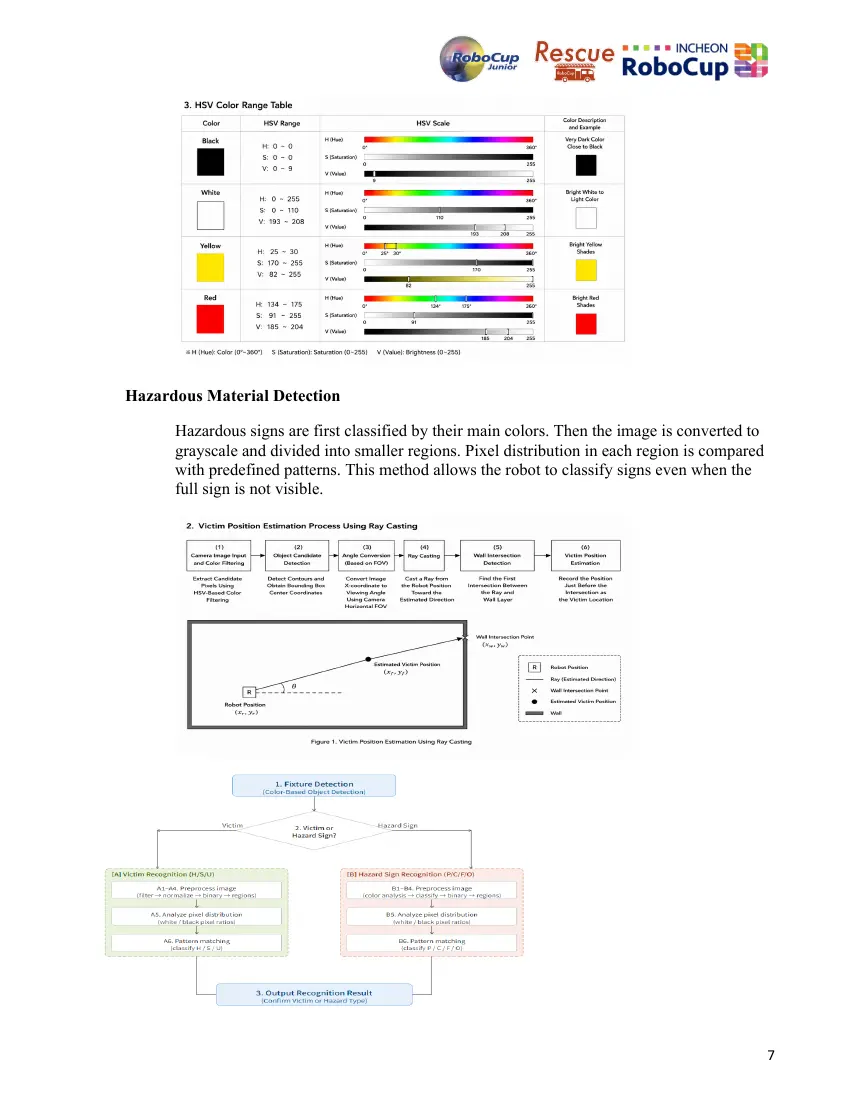
The system uses HSV color filtering for black, white, yellow, and red. Pixels within the
defined ranges become candidate regions. A wall mask removes objects that are not
located on walls.
After filtering, contours and bounding boxes are calculated. The center of the bounding
box is converted into an angle using the camera’s field of view, and ray casting is used to
estimate the object’s position on the map.
For victim classification, the letter area is extracted and divided into upper, middle, and
lower regions. The pixel distribution is compared with predefined patterns to identify the
victim type.
6
Hazardous Material Detection
Hazardous signs are first classified by their main colors. Then the image is converted to
grayscale and divided into smaller regions. Pixel distribution in each region is compared
with predefined patterns. This method allows the robot to classify signs even when the
full sign is not visible.
7
Detection Testing
Detection was tested with different camera directions and incomplete images. The team
chose a color-based method because it was faster and simpler than a complex AI model
while still being reliable in the simulation environment.
d. Mapping
The mapping system combines LiDAR, GPS, gyroscope, and camera data to generate a
real-time map. The map is used for navigation, obstacle avoidance, victim recording, and
return-to-start behavior.
Integer Grid
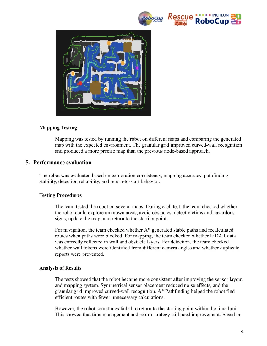
Sensor data is stored in an expandable integer grid. The mapper records walls, obstacles,
floor conditions, victim locations, explored areas, and the robot’s path. LiDAR is mainly
used for walls and obstacles, while cameras are used for floor types and wall tokens.
Because the robot uses continuous coordinate-based navigation instead of tile-based
movement, exact tile boundaries can be difficult to detect. To reduce this issue, the map is
continuously updated with new sensor data.
Granular Grid
The granular grid combines LiDAR data with additional information such as floor type
and structure location. Compared with the previous node-based grid, the granular grid
represents the environment in more detail and improves curved-wall recognition.
After the simulation ends, the granular grid can be converted into the competition’s
Bonus Grid format.
Floor and Obstacle Mapping
Floor types are detected mainly by color. Camera images are converted into a top-view
image using OpenCV’s cv.warpPerspective() function. HSV filters are then used to
identify black holes, swamps, and checkpoints.
Obstacles are detected using LiDAR. Detected points are stored as possible obstacles. If
the same position is detected multiple times, its confidence increases and it is stored as a
wall. Low-confidence points are removed as noise. The pathfinder then uses the
traversable and navigation preference layers to calculate safer paths.
8
Mapping Testing
Mapping was tested by running the robot on different maps and comparing the generated
map with the expected environment. The granular grid improved curved-wall recognition
and produced a more precise map than the previous node-based approach.
5. Performance evaluation
The robot was evaluated based on exploration consistency, mapping accuracy, pathfinding
stability, detection reliability, and return-to-start behavior.
Testing Procedures
The team tested the robot on several maps. During each test, the team checked whether
the robot could explore unknown areas, avoid obstacles, detect victims and hazardous
signs, update the map, and return to the starting point.
For navigation, the team checked whether A* generated stable paths and recalculated
routes when paths were blocked. For mapping, the team checked whether LiDAR data
was correctly reflected in wall and obstacle layers. For detection, the team checked
whether wall tokens were identified from different camera angles and whether duplicate
reports were prevented.
Analysis of Results
The tests showed that the robot became more consistent after improving the sensor layout
and mapping system. Symmetrical sensor placement reduced noise effects, and the
granular grid improved curved-wall recognition. A* Pathfinding helped the robot find
efficient routes with fewer unnecessary calculations.
However, the robot sometimes failed to return to the starting point within the time limit.
This showed that time management and return strategy still need improvement. Based on
9
these results, the team adjusted the pathfinding process and focused on improving
navigation stability.
Overall, the robot performed exploration, mapping, detection, and path planning reliably
across multiple maps. The main improvements compared with the previous version were
sensor noise reduction, better mapping accuracy, and more stable navigation.
6. Conclusion
Team RM developed an autonomous rescue simulation robot that integrates LiDAR, GPS,
gyroscope, and camera sensors to perform exploration, detection, mapping, and return-to-start
behavior. Compared with the previous version, the robot was improved through better sensor
placement, noise-aware mapping, A* navigation, and OpenCV-based detection.
Although return timing still needs improvement, the current system solved many problems from
the previous competition. Through this project, the team gained experience in autonomous
navigation, sensor integration, image processing, mapping, and software-based problem solving.
References
[1] RoboCup Rescue Simulation Website
<https://junior.robocup.org/robocupjuniorrescue-league-simulation/>
[2] NumPy Library Official Website
<https://numpy.org/>
[3] OpenCV Library Official Website
<https://opencv.org/>
[4] A* Algorithm
<https://byte348.com/A-star-algorithm/>
[5] Dijkstra’s Algorithm
<https://www.w3schools.com/dsa/dsa_algo_graphs_dijkstra.php>
[6] OpenCV Library, Geometric Transformations
<https://docs.opencv.org/4.x/da/d6e/tutorial_py_geometric_transformations.html>
[7] OpenCV Library, Changing Colorspaces
<https://docs.opencv.org/4.x/df/d9d/tutorial_py_colorspaces.html>
[8] OpenCV Library, Contour Approximation
<https://docs.opencv.org/3.4/d4/d73/tutorial_py_contours_begin.html>
[9] Red Blob Games, Introduction to A*
<http://theory.stanford.edu/~amitp/GameProgramming/AStarComparison.html>
10
10 pages, rendered as images so they load quickly. The text above is the document's own, extracted from the PDF.
Source code
The team's own source code, 112 KB. It is a download rather than part of this page, because a zip is something you open on your computer. It comes from GitHub, which some school networks block.