
Theseus
Document register
- Poster1 pagePublished
- Presentation videoYouTubePublished
- Bill of materials87 KBPublished
- Team description paper24 pagesPublished
- Engineering journalNot shared
- Source code25 KB · GitHubPublished
Sharing each document is the team's decision. “Not shared” means this team chose not to publish it, or did not submit one — not that it is missing from the archive.
In their words
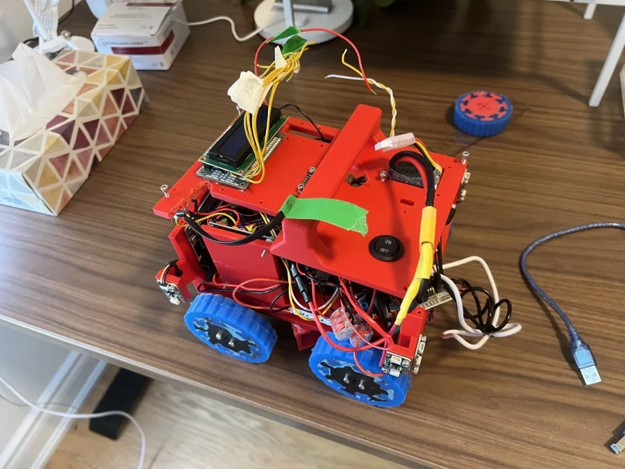
What sets the Theseus Maze Robot apart from competitors utilizes a fusion of information from disparate sensors to accurately and reliably traverse the maze. Instead of using a single type of sensor to control movement, data from the gyro, TOF and magnetic encoder sensors are combined to allow for smooth and precise movement through the maze. The robot uses a state machine as its software architecture for navigating the maze, and uses a 2-D Array consisting of our own custom tile bitset to map out its route. To detect victims, a powerful FOMO network was trained on over a thousand augmented images through an edge impulse pipeline to detect victims. We also have many hardware innovations, including a suspension system for smoother movement in uneven terrain as well as a rotating dispenser allowing for selective dispensing on both sides of the robot. However, our team has placed most of our efforts into improving the software, as we believe that better navigation, movement and detection would give us the advantage over a team with custom hardware, but with worse code.
Poster
Read the text of this document — 1553 words
TEAM MEMBERS & SOCIALS
Theseus- Canada
Baichen Luo - Team Lead (Electronics & Computer Vision)
Leo Tiralongo - Mechanical Design & Electrical Assembly
Christopher Shu - Software Architecture & Navigation
Lucas Cai - BFS Algorithm Programmer
Documentation link: https://github.com/Arsur24/Theseus/tree/main
[St Andrew’s College — RoboCup Junior Rescue Maze Code link: https://github.com/Chrisyyyys/Robocup-Junoir-Theseus
INTRODUCTION DISTANCE SENSING CHASSIS & MATERIALS POWER SYSTEM
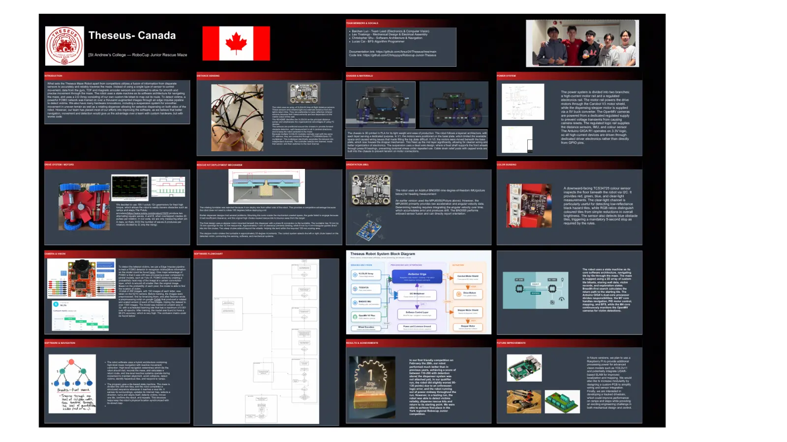
What sets the Theseus Maze Robot apart from competitors utilizes a fusion of information from disparate
sensors to accurately and reliably traverse the maze. Instead of using a single type of sensor to control
movement, data from the gyro, TOF and magnetic encoder sensors are combined to allow for smooth and
precise movement through the maze. The robot uses a state machine as its software architecture for navigating The power system is divided into two branches:
the maze, and uses a 2-D Array consisting of our own custom tile bitset to map out its route. To detect victims, a a high-current motor rail and a regulated
powerful FOMO network was trained on over a thousand augmented images through an edge impulse pipeline electronics rail. The motor rail powers the drive
to detect victims. We also have many hardware innovations, including a suspension system for smoother motors through the Carobot V3 motor shield,
movement in uneven terrain as well as a rotating dispenser allowing for selective dispensing on both sides of the The robot uses an array of VL53L0X time-of-flight distance sensors. while the dispensing stepper motor is supplied
robot. However, our team has placed most of our efforts into improving the software, as we believe that better These sensors emit infrared light and estimate distance from the
navigation, movement and detection would give us the advantage over a team with custom hardware, but with
light’s return time. They are preferable to basic reflective infrared via a 5V buck converter. The OpenMV cameras
sensors because their measurements are less dependent on the
worse code. visible colour of the wall.
are powered from a dedicated regulated supply
The README identifies the VL53L0X as the principal distance to prevent voltage transients from causing
sensor and emphasizes the organizational advantages of using I²C
devices. camera resets. The regulated logic rail supplies
The sensors are positioned around the chassis to provide forward the distance sensors, IMU, and colour sensor.
obstacle detection, wall measurement in all 4 cardinal directions,
and to keep the robot centered in the maze. The Arduino GIGA R1 operates on 3.3V logic,
Because multiple VL53L0X modules normally start with the same The chassis is 3D printed in PLA for its light weight and ease of production. The robot follows a layered architecture, with
I²C address, they are connected through a TCA9548A/Qwiic I²C each layer serving a dedicated purpose. In V1, the motors were positioned on the base plate, which limited the available so all high-current devices are driven through
multiplexer. The multiplexer electrically separates the sensors into space and caused wiring issues that made fitting the top plate difficult. In V2, the motors were moved beneath the base dedicated driver electronics rather than directly
independent channels. The controller selects one channel, reads
that sensor, and then switches to the next channel.
plate, which now houses the dropper mechanism. This freed up the mid layer significantly, allowing for cleaner wiring and from GPIO pins.
better organization of electronics. The suspension uses a dead axle design, where a fixed shaft supports the front wheels
through press-fit bearings, preventing torsional stress under repeated use. Cable strain relief posts with capped ends are
built into the chassis to prevent tension on motor connections.
DRIVE SYSTEM / MOTORS RESCUE KIT DEPLOYMENT MECHANISM ORIENTATION (IMU) COLOR SENSING
A downward-facing TCS34725 colour sensor
The robot uses an Adafruit BNO055 nine-degree-of-freedom IMU(picture
below) for heading measurement
inspects the floor beneath the robot via I2C. It
. provides red, green, blue, and clear-light
An earlier version used the MPU6050(Picture above). However, the measurements. The clear-light channel is
[Color Sensor Pho
We decided to use 195:1 polulu 12v gearmotors for their high MPU6050 primarily provides raw acceleration and angular-velocity data. particularly useful for detecting low-reflectance
torque, which allows the robot to easily travers obstacles such as The rotating turntable was selected because it can deploy kits from either side of the robot. This provides a competitive advantage because Determining heading requires integrating the angular velocity over time, black hazard tiles, while RGB ratios distinguish
ramps and steps.The Polulu the robot does not need to rotate 180 degrees before deploying a kit. which accumulates error and produces drift. The BNO055 performs
encoders(https://www.pololu.com/product/1523) produce two coloured tiles from simple reductions in overall
onboard sensor fusion and can directly report orientation.
alternating square waves, A and B, when overlapped creates 20 Earlier dispenser designs had several problems. Mounting the motor inside the mechanism wasted space, the guide failed to engage because brightness. The sensor also detects blue obstacle
pulses per rotation. In our code, we are only measuring when pin it had insufficient clearance, and the original high chutes caused rescue kits to bounce away from the target.
tiles, triggering a mandatory 5-second stop as
A rises, so thats 20/2( the number of waves A produces per
rotation) divided by 2( only the rising).
The final design uses a stepper motor mounted beneath the dispenser with a press-fit connection to the turntable. The turntable has 19 mm by required by the rules.
19 mm openings for the 10 mm rescue kits. Approximately 1 mm of clearance prevents binding, while 8 mm by 4 mm triangular guides direct
kits into the chutes. Two steep chutes extend beyond the wheels, helping kits land within the required 150 mm scoring area.
The stepper motor rotates the turntable in approximately 22-degree increments. The control system selects the left or right chute based on the
detected victim, connecting the sensing, software, and mechanical systems.
CAMERA & VISION SOFTWARE FLOWCHART
To detect the lettered victims, we use a Edge Impulse pipeline
to train a FOMO detector to recognize victims(More information The robot uses a state machine as its
on the model could be found here). One major advantage of core software architecture, navigating
FOMO is that it uses x30 less processing power compared to tile by tile through the maze. The maze
similar models, such as Yolo v5. FOMO works by creating a
probabilistic heat map of the image at a certain convolution
is mapped using a 2D array of custom
layer, which is around x8 smaller than the original image. tile bitsets, storing wall data, victim
Based on the probability of each pixel, the model is able to find records, and exploration states.
the location of victim. Breadth-first search calculates the
A total of 450 images, with 150 images of each letter, was return path to the starting tile. The
taken on the K210 camera. Before training, the images were Arduino GIGA's dual-core processor
preprocessed, first by binarizing them, and after Baichen wrote
divides responsibilities: the M7 core
a preprocessing script on google Collab that produced a rotated
and scaled version of each of the images, tripling the dataset to handles navigation, PID motor control,
over 1300 images. The model was trained on a batch size of mapping, and BFS, while the M4 core
32, with a scheduled learning rate that has a maximum of 0.001 continuously monitors the OpenMV
over 40 epochs. After training, the model was found to have a cameras for victim detections.
96.2% accuracy, which is very high. The confusion matrix could
be found below:
SOFTWARE & NAVIGATION RESULTS & ACHIEVEMENTS FUTURE IMPROVEMENTS
In future versions, we plan to use a
In our first friendly competition on Raspberry Pi to provide additional
The robot software uses a hybrid architecture combining
high-level maze navigation with reactive movement
February the 28th, our robot processing power for advanced
correction. High-level navigation determines which tile the performed much better than in vision models such as YOLOv11
robot should visit, records the maze, and calculates a previous years, achieving a score of
and potentially integrate LiDAR-
return route, and low-level reactive systems operate during between 110-200 with detection
movement to maintain alignment, avoid collisions, detect
based SLAM for improved
alone( the dispenser system was
victims, identify hazardous tiles, and respond to ramps. localization and mapping. We would
not attached yet). In our qualifier
run, the robot did slightly worse( 95- also like to increase modularity by
The program uses a tile-based state machine. The maze is designing a custom PCB to simplify
divided into 300 mm tiles, and the robot completes a 130 points) due to an unforeseen
logic error, and the robot running wiring and sensor integration.
structured sequence whenever it reaches a new tile. It
senses its surroundings, updates its internal map, selects a out of power midway throughout the Finally, we are interested in
direction, turns and aligns itself, detects victims, moves run. However, in a testing run, the developing a tracked drivetrain,
one tile, confirms the result, and repeats. This structure robot was able to detect victims which could improve performance
helps keep the robot’s physical location synchronized with reliably, dispense rescue kits and on ramps and steps while providing
its stored map.
return to its starting point. We were an exciting engineering challenge in
able to achieve first place in the both mechanical design and control.
York regional Robocup Junior
competition.
1 page, rendered as images so they load quickly. The text above is the document's own, extracted from the PDF.
Presentation video
Hosted on YouTube. The player loads only when you press play.
Bill of materials
Shown as the original PDF, because this one is smaller that way and its text stays selectable and searchable.
Team description paper
Show the remaining 21 pages
Read the text of this document — 6712 words
Theseus
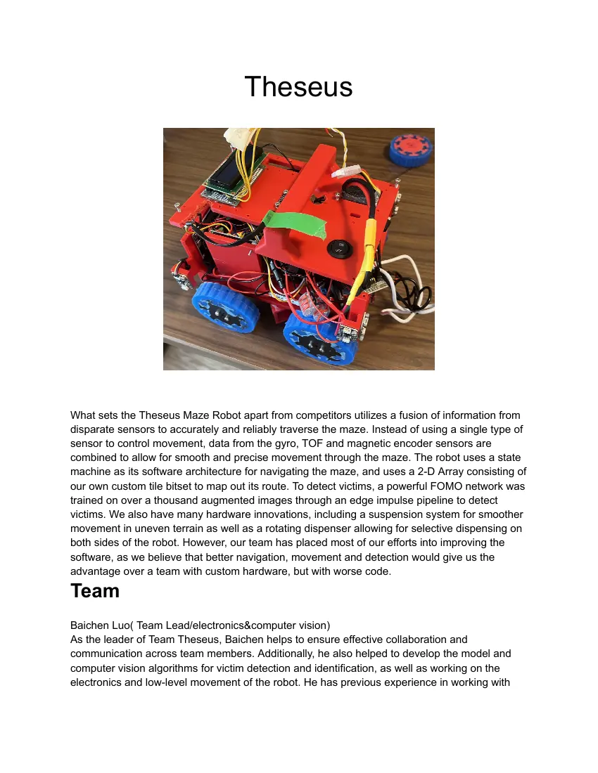
What sets the Theseus Maze Robot apart from competitors utilizes a fusion of information from
disparate sensors to accurately and reliably traverse the maze. Instead of using a single type of
sensor to control movement, data from the gyro, TOF and magnetic encoder sensors are
combined to allow for smooth and precise movement through the maze. The robot uses a state
machine as its software architecture for navigating the maze, and uses a 2-D Array consisting of
our own custom tile bitset to map out its route. To detect victims, a powerful FOMO network was
trained on over a thousand augmented images through an edge impulse pipeline to detect
victims. We also have many hardware innovations, including a suspension system for smoother
movement in uneven terrain as well as a rotating dispenser allowing for selective dispensing on
both sides of the robot. However, our team has placed most of our efforts into improving the
software, as we believe that better navigation, movement and detection would give us the
advantage over a team with custom hardware, but with worse code.
Team
Baichen Luo( Team Lead/electronics&computer vision)
As the leader of Team Theseus, Baichen helps to ensure effective collaboration and
communication across team members. Additionally, he also helped to develop the model and
computer vision algorithms for victim detection and identification, as well as working on the
electronics and low-level movement of the robot. He has previous experience in working with
Artificial intelligence and has interned at Fudan University in Shanghai, where he helped
postgraduate students collect data for a robotics project.
Leo(CAD design/mechanical)
Leo handles the mechanical design and electrical assembly of the robot, responsible for
designing the chassis and physical structure in Fusion 360, managing 3D printed components,
and connecting all electrical components through soldering and protoboard work. He has
previous experience as a team leader in the VEX V5 competition and founded an FPV drone
building program at his school. Outside of the team, his personal projects include designing a
custom FPV drone frame and building a 6 DOF robotic arm.
Chris( Software architecture)
Chris’s main contribution was developing the robot’s navigation software. Chris designed the
state machine that controls sensing, mapping, victim detection, path planning, and movement.
To support navigation, Chris developed the 2-D array based map system that utilizes a custom
tile data structure. Together, these systems enable efficient exploration, hazard avoidance, and
reliable autonomous navigation.
Lucas (Algorithm Programmer)
Lucas is a programmer on the team who focuses on mapping, pathfinding, and software
optimization. Lucas developed algorithms such as BFS and works with memory reallocation
techniques to help the robot navigate efficiently and reliably.
Keywords
Arduino Giga
BFS
FOMO detection
Computer Vision
State Machine
PID control
Bitset Tile data structure
Memory saving.
Multicore Threading
Encoder-controlled movement
Overall project plan.
From our first year participating in the Robocup Junior Rescue Maze competition last year, team
Theseus realized the importance of good hardware for ensuring success. This is because all
software is ultimately supported and limited by the foundational hardware it lies on. Because of
this realization, team Theseus decided to spend more time planning and designing the robot this
year. One major change from last year was the use of a soldered protoboard instead of a
breadboard, ensuring more reliable electronic connections. Therefore, the first major milestone
was to complete our robot before any software could be tested. Because our first competition
was in February, it was essential the robot was built before Christmas so that we were able to
start developing code. However, this was hampered by the need to choose the camera(
OpenMV H7 plus vs the K210 architecture we used last year) on the robot, which became a
roadblock and a minor milestone. After Baichen was able to verify the model pipeline for the
OpenMV camera was viable by November 2025, Leo was able to finish the CAD file. However,
we were behind schedule as the robot was not able to be completed before Christmas.
After Christmas break, where Baichen finished the robot and connected the electronics on the
protoboard, the next milestone was to develop the software architecture for the navigation of the
robot. This task was delegated to Christopher and Lucas, while Baichen handled the
movement(forward and turning) and control of the robot through the sensors. On the day of the
competition the robot ran very smoothly and we were very satisfied. However, with the release
of the 2026 rescue maze rules, and the changed victims, team Theseus was forced to rewrite its
computer vision code. Although the edge impulse pipeline made it simple to retrain a model to
identify letter victims, a lot of trial and error was needed to create a reliable algorithm to detect
the cognitive victims( adjusting color bounds). Moreover, the robot struggled to detect victims
while moving, because of the large number of blocking operations in the movement loop, so a
decision was made to switch to an multicored processor( Arduino Giga) in the future. Because
there were a couple of hardware flaws in the current robot, such as not being able to cross
steps due to the low ground clearance of the robot, the team agreed on the need to develop a
new robot if we were to be competitive in the world’s level of competition. Although the CAD was
completed quickly, the awkward positioning of electronic components made the robot difficult to
wire, increasing the time needed to build and test the capabilities of the new robot. Our current
robot was not fully completed until June. Switching processors bought challenges of its own, as
the code had to be modified significantly to account for the specialization of tasks for each core.
Integration plan
The development of Theseus required close collaboration between team members, as many
tasks depended on one another. Before the CAD design could be finalized, we first had to verify
that the OpenMV H7 Plus could support our victim-detection pipeline. Once the camera solution
was proven viable, the mechanical design and electronics layout could proceed with confidence.
As development progressed, team members worked on mechanical, electrical, and software
systems in parallel while regularly sharing feedback from testing. Hardware and software were
gradually integrated, with sensor feedback, movement control, victim detection, and rescue-kit
deployment combined into a single system. Later in the season, advanced features such as the
tile-based mapping system and Breadth-First Search (BFS) return-home algorithm were added.
Through continuous testing and collaboration, individual contributions were successfully
integrated into a complete autonomous robot capable of navigating the maze and completing
rescue tasks.
Mechanical Design and Manufacturing
Our mechanical design was developed through three main design sprints. Each sprint focused
on a major subsystem, using prototypes and testing results to improve the final robot.
This year, we first focused on redesigning the robot’s chassis and drivetrain. The motors were
moved beneath the bottom electronics layer, creating more internal space for sensors, wiring,
and the rescue-kit dispenser. The chassis provides over 20 mm of ground clearance, helping
the robot travel over obstacles without the frame contacting the ground.
The robot uses four 195:1 geared motors with 80 mm wheels. Independent control of the left
and right wheels allows differential steering and zero-radius turns, which are important when
navigating narrow maze intersections.
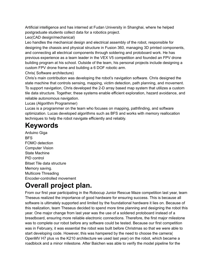
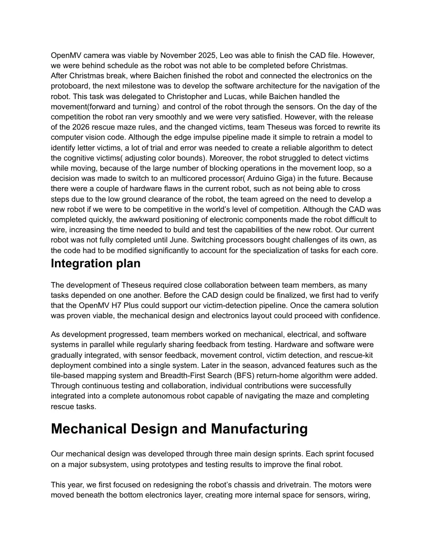
A custom dead-axle suspension system was developed using bearings(pictured above), fixed
axles, and integrated motor mounts. The design was inspired by the S3R5 suspension system
used in 2025, but was adapted for our robot. During development, the suspension wedge was
moved upward to improve ground clearance and reduce the amount of internal space it
occupied.
Cable management was integrated directly into the chassis using cable channels, zip-tie holes,
countersunk fasteners, and strain-relief posts. Testing showed that the strain-relief system
removed tension from the motor connections. However, the posts were slightly too short,
identifying a possible improvement for future versions.
The second development phase focused on creating a reliable mechanism for deploying rescue
kits. Three concepts were considered: a PEZ-style dispenser that our team used last
year(Google Patents Link ), a rotating paddle, and a turntable similar to a gumball machine.
The rotating turntable was selected because it can deploy kits from either side of the robot. This
provides a competitive advantage because the robot does not need to rotate 180 degrees
before deploying a kit.
Earlier dispenser designs had several problems. Mounting the motor inside the mechanism
wasted space, the guide failed to engage because it had insufficient clearance, and the original
high chutes caused rescue kits to bounce away from the target.
The final design uses a stepper motor mounted beneath the dispenser with a press-fit
connection to the turntable. The turntable has 19 mm by 19 mm openings for the 10 mm rescue
kits. Approximately 1 mm of clearance prevents binding, while 8 mm by 4 mm triangular guides
direct kits into the chutes. Two steep chutes extend beyond the wheels, helping kits land within
the required 150 mm scoring area.
The stepper motor rotates the turntable in approximately 22-degree increments. The control
system selects the left or right chute based on the detected victim, connecting the sensing,
software, and mechanical systems.
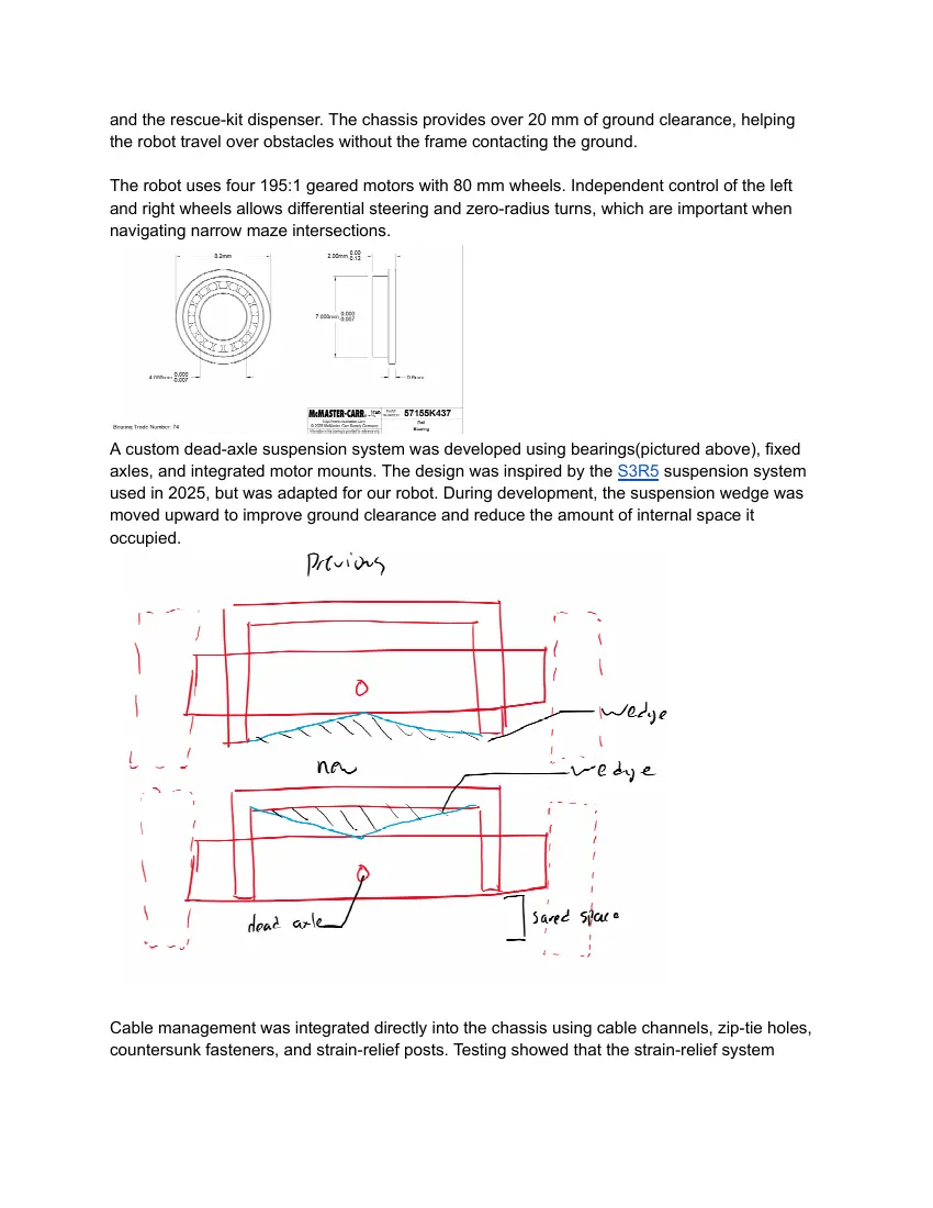
The third sprint focused on designing rescue kits that land reliably after deployment. A weighted,
self-righting cube was developed using the same principle as a roly-poly toy.
The first prototype was made from cardboard and contained metal nuts. During testing, it was
dropped from approximately 30 mm. The prototype did not roll far enough because its faces
were uneven, the nuts were too light, and the centre of gravity was too high.
Based on these results, the final concept uses a uniform 3D-printed 10 mm cube with denser
metal pellets positioned lower inside it. This lowers the centre of gravity and improves the
chance that the rescue kit lands correctly after leaving the chute.
Testing and Design Validation
Testing directly influenced each sprint. Chassis testing checked obstacle clearance and wheel
movement. Suspension testing evaluated wheel contact and motor support. Cable testing
identified the need for improved strain-relief posts. Dispenser testing resulted in increased guide
clearance, a bottom-mounted motor, and lower chutes. Rescue-kit drop testing led to a denser
and more balanced design.
Further validation includes repeated obstacle crossings, narrow turning tests, deployments from
both sides, and rescue-kit drop tests. A successful design must avoid chassis impacts, maintain
wheel contact, protect wiring, prevent dispenser jams, and consistently place rescue kits inside
the scoring area.
Electronics
Electronic Design and Development Tools
The repository’s electronics documentation currently includes a sensor bill of materials and a
system block diagram, while the README describes the principal sensors, control architecture,
mapping system, and software organization. The following section expands that material and
incorporates the migration from the Arduino Mega 2560 to the Arduino GIGA R1 WiFi.
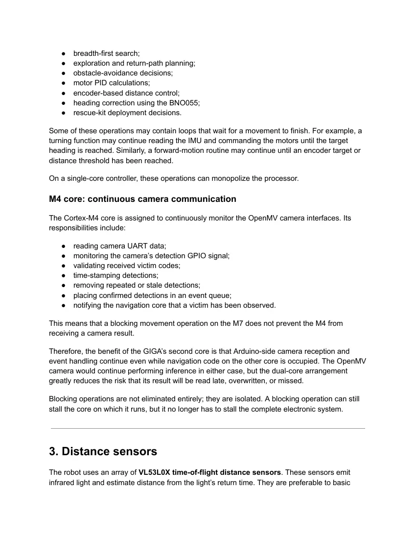
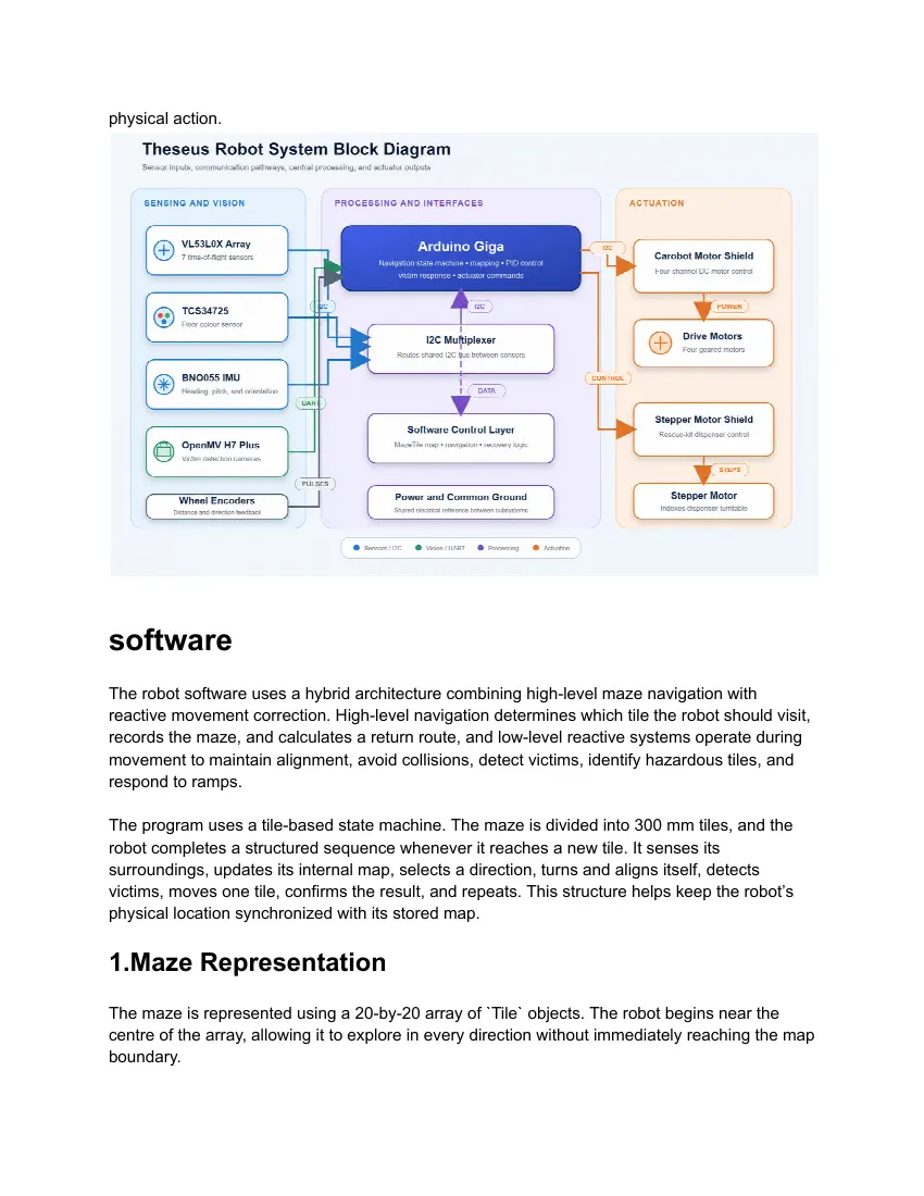
1. Overall electronic architecture
Theseus uses a distributed electronic architecture rather than expecting one device to perform
all the processing, including the autonomous code and the image processing. The Arduino
GIGA R1 WiFi acts as the main real-time controller, while the OpenMV camera modules perform
image acquisition and neural-network inference. The OpenMV cameras process their images
locally and transmit compact results such as Phi, Omega, or Psi to the GIGA. This avoids
sending full images to the main controller and greatly reduces communication bandwidth.
Distance, colour, orientation, and encoder sensors provide environmental and motion feedback.
Motor drivers and dispensing actuators convert the controller’s commands into physical
movement.
Here above is diagram for the signal/power flow of the robot
2. Main controller
The original controller was an Arduino Mega 2560. It was initially selected because it provides
many GPIO pins and four hardware UART interfaces, which are useful for a robot containing
numerous sensors, motor-control signals, encoders, and cameras. Moreover, it was simple to
use, and met our needs. However, the Mega’s ATmega2560 is a single-core, 16 MHz, 8-bit
processor with only 8 KB of SRAM and 256 KB of program flash. This limits the possibilities for
programing( especially when the maze gets larger). Moreover, the large amount of blocking
functions made sensing extremely slow( 100-200ms per sense), which slows down the
response time of the robot. A blocking motor routine, a delay, a long I²C transaction, or a loop
waiting for a turn to finish could prevent the controller from reading camera messages at the
required time.
Those limitations became increasingly important as the software grew. The robot must hold a 20
× 20 map, tile information, wall data, victim records, exploration states, planned paths, sensor
readings, PID variables, and communication buffers. The repository already uses compact
bitset-based tile objects to conserve memory, and it applies breadth-first search when
calculating a route back to the starting tile. Even still, a simple 20x20 map took up 73% of
available memory. Moreover, the robot often struggled to stop after detecting victims.
Why we switched to Arduino GIGA R1 WiFi
To remove these restrictions, we migrated the main controller to the Arduino GIGA R1 WiFi. It
retains the Mega physical form factor and large number of pins but uses the much more capable
STM32H747XI processor.
The GIGA provides:
● a 480 MHz Arm Cortex-M7 core;
● a 240 MHz Arm Cortex-M4 core;
● 1 MB of internal RAM;
● 2 MB of internal flash;
● 8 MB of onboard SDRAM;
● 16 MB of onboard NOR flash;
● four UART interfaces;
● three I²C buses;
● two SPI buses;
● 76 digital I/O pins.
The increase from 8 KB of SRAM on the Mega to 1 MB of internal RAM plus 8 MB of external
SDRAM gives the robot substantially more space for maps, queues, pathfinding structures,
sensor histories, and debugging information. The additional flash memory also removes much
of the pressure caused by large sensor libraries and increasingly complex control software.
The GIGA is not merely a faster replacement. Its most important architectural advantage is its
dual-core processor.
The STM32H747 processor of the Arduino Giga contains two independently programmable
processors. Arduino identifies them as the high-performance M7 core and the secondary M4
core. The two cores can run separate programs and communicate using remote procedure calls
or shared messages.
For Theseus, the processing responsibilities can be divided as follows.
M7 core: navigation and motion control
The Cortex-M7 core handles the computationally intensive and timing-sensitive navigation
functions:
● tile-state machine;
● maze mapping;
● breadth-first search;
● exploration and return-path planning;
● obstacle-avoidance decisions;
● motor PID calculations;
● encoder-based distance control;
● heading correction using the BNO055;
● rescue-kit deployment decisions.
Some of these operations may contain loops that wait for a movement to finish. For example, a
turning function may continue reading the IMU and commanding the motors until the target
heading is reached. Similarly, a forward-motion routine may continue until an encoder target or
distance threshold has been reached.
On a single-core controller, these operations can monopolize the processor.
M4 core: continuous camera communication
The Cortex-M4 core is assigned to continuously monitor the OpenMV camera interfaces. Its
responsibilities include:
● reading camera UART data;
● monitoring the camera’s detection GPIO signal;
● validating received victim codes;
● time-stamping detections;
● removing repeated or stale detections;
● placing confirmed detections in an event queue;
● notifying the navigation core that a victim has been observed.
This means that a blocking movement operation on the M7 does not prevent the M4 from
receiving a camera result.
Therefore, the benefit of the GIGA’s second core is that Arduino-side camera reception and
event handling continue even while navigation code on the other core is occupied. The OpenMV
camera would continue performing inference in either case, but the dual-core arrangement
greatly reduces the risk that its result will be read late, overwritten, or missed.
Blocking operations are not eliminated entirely; they are isolated. A blocking operation can still
stall the core on which it runs, but it no longer has to stall the complete electronic system.
3. Distance sensors
The robot uses an array of VL53L0X time-of-flight distance sensors. These sensors emit
infrared light and estimate distance from the light’s return time. They are preferable to basic
reflective infrared sensors because their measurements are less dependent on the visible colour
of the wall.
The README identifies the VL53L0X as the principal distance sensor and emphasizes the
organizational advantages of using I²C devices.
The sensors are positioned around the chassis to provide forward obstacle detection, wall
measurement in all 4 cardinal directions, and to keep the robot centered in the maze.
●
Because multiple VL53L0X modules normally start with the same I²C address, they are
connected through a TCA9548A/Qwiic I²C multiplexer. The multiplexer electrically separates the
sensors into independent channels. The controller selects one channel, reads that sensor, and
then switches to the next channel.
This arrangement provides several advantages:
● identical-address sensors can operate on the same controller;
● only one SDA/SCL pair is required at the GIGA;
● wiring is easier to organize;
● a malfunctioning sensor channel can be isolated;
● individual sensors can be tested separately.
The distance readings feed both the deliberative and reactive layers. The mapping system uses
them to determine whether walls exist around the current tile, while the reactive controller uses
more frequent measurements for wall following and collision prevention.
4. Inertial measurement unit
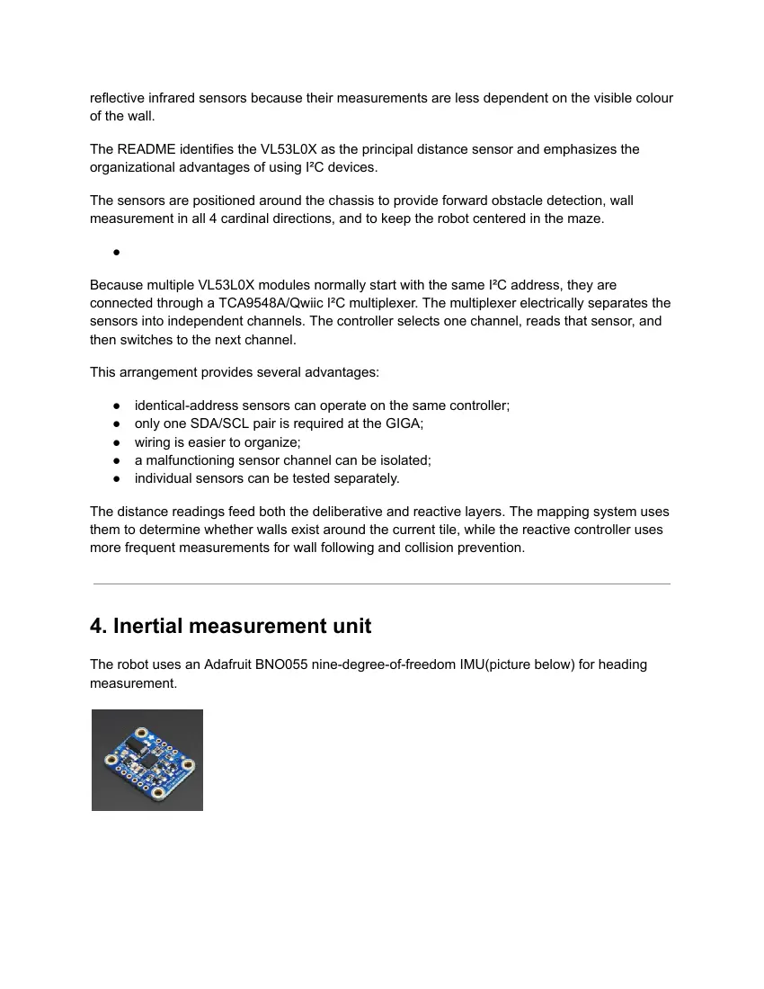
The robot uses an Adafruit BNO055 nine-degree-of-freedom IMU(picture below) for heading
measurement.
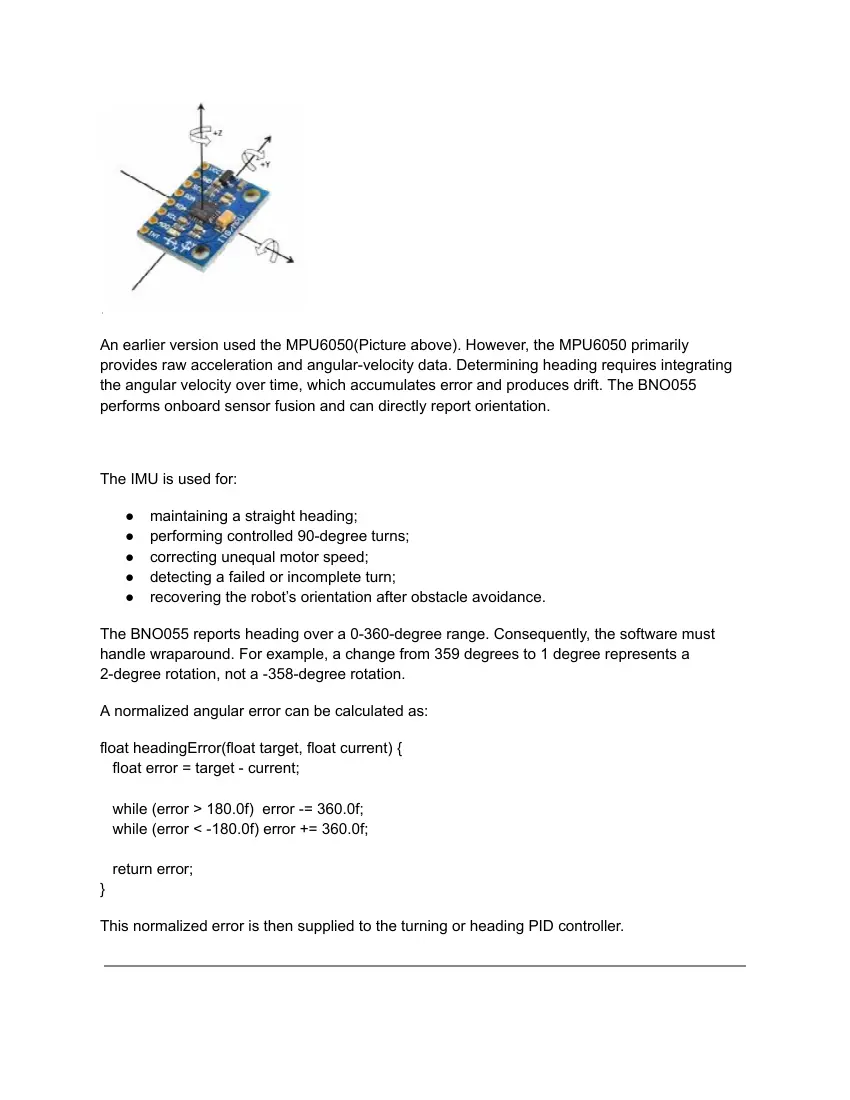
An earlier version used the MPU6050(Picture above). However, the MPU6050 primarily
provides raw acceleration and angular-velocity data. Determining heading requires integrating
the angular velocity over time, which accumulates error and produces drift. The BNO055
performs onboard sensor fusion and can directly report orientation.
The IMU is used for:
● maintaining a straight heading;
● performing controlled 90-degree turns;
● correcting unequal motor speed;
● detecting a failed or incomplete turn;
● recovering the robot’s orientation after obstacle avoidance.
The BNO055 reports heading over a 0-360-degree range. Consequently, the software must
handle wraparound. For example, a change from 359 degrees to 1 degree represents a
2-degree rotation, not a -358-degree rotation.
A normalized angular error can be calculated as:
float headingError(float target, float current) {
float error = target - current;
while (error > 180.0f) error -= 360.0f;
while (error < -180.0f) error += 360.0f;
return error;
}
This normalized error is then supplied to the turning or heading PID controller.
5. Wheel encoders
Magnetic encoders are fitted to the drive system to measure wheel rotation. Unlike distance
sensors, which measure the environment, encoders directly measure the movement of the
wheels.Encoder signals are connected to interrupt-capable GIGA pins. Each pulse increments a
counter, allowing the controller to estimate distance:
Encoder interrupt routines are kept very short. They should normally increment a volatile
counter and return immediately; distance calculations and PID operations are performed outside
the interrupt service routine.
6. Colour sensor
A downward-facing TCS34725 colour sensor is used to inspect the floor beneath the robot.
The sensor provides red, green, blue, and clear-light measurements through I²C.
Its main functions are: detecting black hazard tiles and blue obstacle tiles
● distinguishing dark tiles from shadows;
● detecting special coloured tiles when required;
● triggering an immediate stop and backtracking procedure.
The clear-light channel is particularly useful for detecting low-reflectance black surfaces. RGB
ratios can then be used to distinguish a genuinely coloured tile from a simple reduction in overall
brightness.
The sensor is mounted close to the floor and shielded from side lighting. Calibration is
performed under competition lighting using samples of normal, black, and coloured floor
materials.
7. Camera and victim-detection subsystem
The robot uses OpenMV camera modules as dedicated vision processors. Instead of
transferring raw camera frames to the GIGA, each OpenMV runs its own image-processing
program and transmits only the classification result.
The camera identifies letter victims such as:
● Φ - harmed victim;
● Ψ - stable victim;
● Ω - unharmed victim.
It also contains colour-threshold logic for coloured victim markers and sends the final result to
the main controller.
Using the OpenMV as an edge-vision processor has several benefits:
● neural-network inference does not consume processor processing time;
● only a few bytes need to pass through UART;
● camera code can be developed independently;
● camera failure does not directly stop basic navigation;
● the cameras continue processing while the robot is moving.
The GIGA’s M4 core receives and queues the results, while the M7 core decides whether the
robot should stop, determine the victim’s side, dispense a kit, and record the victim in the map.
8. Communication interfaces
The electronic design deliberately uses a small number of standard communication protocols.
I²C
I²C connects the VL53L0X distance sensors, TCS34725 colour sensor, BNO055 IMU, and I²C
multiplexer. This reduces the required number of signal wires and makes the electronics easier
to route and diagnose. The README identifies this shared-protocol strategy as an important
design choice.
UART
UART connects the OpenMV cameras to the GIGA. The camera code currently configures its
link at 115200 baud.
A robust message can contain more than a single character:
<camera ID, victim class, confidence, frame number, checksum>
This makes it possible to reject corrupted messages, distinguish the left and right cameras, and
avoid deploying multiple kits for the same detection.
Interrupt-driven GPIO
Encoder channels are read through hardware interrupts.
PWM and motor-control signals
The motor driver receives speed and direction commands from the GIGA. PWM controls the
effective motor voltage and therefore motor speed, while direction inputs determine forward or
reverse rotation.
9. Actuators
Drive motors
Theseus uses four geared DC motors in a differential-drive configuration. The two motors on
each side operate together. The GIGA does not power the motors directly. Its control signals are
sent to the Carobot V3 motor shield, which is controlled via I2C. The motor shield provide the
current required by the motors and protect the controller from the motor supply.
Motor control combines three types of feedback:
● encoders measure wheel rotation;
● the BNO055 measures heading;
● the VL53L0X sensors measure the robot’s relationship to nearby walls.
This is more reliable than relying on any one sensor alone.
Rescue-kit dispenser
A separate actuator(28BYJ-48 Stepper motor) operates the rescue-kit dispensing mechanism.
The controller activates it after the camera identifies a victim and the navigation system confirms
the victim’s location and side.
11. Power subsystem
The power system is divided into a high-current actuator branch and a regulated electronics
branch.
Battery
│
├── Main switch and protection
│
├── Motor-power rail ──► motor drivers/microcontroller ──► drive motors
│
|── dispensing Stepper motor( Need 5v buck)
├── OpenMV cameras
└── Regulated logic rail from microcontroller
├── distance sensors
├── IMU and colour sensor
This separation prevents rapid changes in motor current from directly disturbing sensitive
sensors and processors.
The GIGA uses 3.3 V logic. Its official documentation specifies 3.3 V I/O logic and warns that
the current available from an individual I/O pin is limited. Motors, servos, and other high-current
devices must therefore be driven through dedicated driver electronics rather than from GPIO
pins. Moreover, a fuseThe OpenMV cameras should preferably be powered from a properly
rated regulated supply rather than relying on the GIGA’s logic rail. Camera inference can create
short current transients, and an inadequate regulator may cause camera resets or corrupted
UART messages.
Result of the GIGA upgrade
The transition from the Arduino Mega to the Arduino GIGA provides three major improvements.
First, the larger memory capacity allows the software to maintain more extensive map,
pathfinding, sensor, and diagnostic data without operating close to the controller’s memory limit.
Second, the much faster M7 processor provides greater computational headroom for BFS,
mapping, PID control, obstacle avoidance, and future navigation algorithms.
Third, the second M4 core allows continuous reception of camera results while the M7 performs
movement and planning operations. Consequently, a blocking turn, forward-motion loop, or
path-planning calculation on the navigation core does not prevent the camera-communication
core from recording a victim detection.
This upgrade changes the main controller from a single sequential processor into a small
real-time distributed system: the OpenMV modules perform visual inference, the M4 core
supervises continuous perception communication, and the M7 core controls navigation and
physical action.
software
The robot software uses a hybrid architecture combining high-level maze navigation with
reactive movement correction. High-level navigation determines which tile the robot should visit,
records the maze, and calculates a return route, and low-level reactive systems operate during
movement to maintain alignment, avoid collisions, detect victims, identify hazardous tiles, and
respond to ramps.
The program uses a tile-based state machine. The maze is divided into 300 mm tiles, and the
robot completes a structured sequence whenever it reaches a new tile. It senses its
surroundings, updates its internal map, selects a direction, turns and aligns itself, detects
victims, moves one tile, confirms the result, and repeats. This structure helps keep the robot’s
physical location synchronized with its stored map.
1.Maze Representation
The maze is represented using a 20-by-20 array of `Tile` objects. The robot begins near the
centre of the array, allowing it to explore in every direction without immediately reaching the map
boundary.
Each tile stores its walls, travelled paths, discovery status, exploration status, victim status,
visited status, blue-tile status, and tile type. Main V3 also includes experimental properties for
upward and downward floor connections.
Directions are represented numerically throughout the program. North is zero, east is one, south
is two, and west is three. This allows the software to calculate rotated and opposite directions
using simple mathematical operations. For example, adding two and applying modulo four
calculates the opposite direction.
2.MazeTile Bitset
Each `Tile` object contains a custom sixteen-bit bitset. The bitset packs multiple true-or-false
properties into individual bits rather than storing each property as a separate Boolean variable.
This reduces memory usage, which is important because the Arduino Mega has limited SRAM
and must store information for up to 400 tiles.
The custom bitset stores sixteen bits inside two eight-bit bytes. When the program needs to
read or change a property, it calculates which byte contains the required bit and its position
inside that byte. A bit mask then reads or changes only that bit without affecting the other stored
properties.
Bits zero to three store whether walls exist to the north, east, south, and west. Bits four to seven
store whether the robot has travelled through the corresponding north, east, south, and west
edges.
Walls and travelled edges are stored separately because they describe different conditions. A
wall bit indicates that movement is physically blocked. An edge bit indicates whether the robot
has already travelled through an open route. A direction can therefore contain no wall while still
having an untravelled edge, meaning it is an available unexplored route.
Bit eight records whether a tile has been discovered. Bit nine records whether the tile is fully
explored. Bit ten records whether a victim has already been detected or serviced at the tile. Bit
eleven records whether the robot has visited the tile. Bit twelve records whether the tile is blue.
Main V3 uses bits thirteen and fourteen for experimental multi-floor navigation. These bits
identify upward and downward connections between floors. Bit fifteen remains available for
future expansion.
The tile type is stored separately from the bitset because it must represent more than two
conditions. Tile types include blank, blue, checkpoint, black, and stair.
When the robot travels between two tiles, the travelled edge is updated in both locations. For
example, after travelling east, the eastern edge of the original tile and the western edge of the
destination tile are both marked as travelled. This keeps the map consistent regardless of which
direction the corridor is later approached from.
This component of our program was written with the help of AI tools.
3.Mapping Process
At startup, every tile is initialized as undiscovered, unvisited, and unexplored. All wall and edge
bits begin as false, and every tile type begins as blank. The starting tile is then marked as
discovered.
Whenever the robot enters a tile, its time-of-flight sensors detect walls relative to the robot’s
body. These measurements describe the front, right, back, and left sides. However, the map
stores walls using fixed global directions.
The software converts relative sensor readings into north, east, south, and west using the
robot’s current heading. If the robot is facing east, its front sensor represents the eastern wall,
its right sensors represent the southern wall, and its left sensors represent the northern wall.
This conversion allows the map to remain consistent when the robot approaches the same tile
from different directions.
After sensing, the current tile is marked as discovered and visited. The software checks every
direction without a wall. If all open directions have already been travelled, the tile is marked as
fully explored.
4.Direction Selection Logic
Main V3 uses a local exploration strategy to select its next direction. It calculates which global
directions correspond to forward, right, left, and backward based on its current heading.
The robot normally prioritizes moving forward, followed by right and then left. It first searches for
a direction that is inside the map, has no wall, has not previously been travelled, leads to an
unvisited tile, and is not known to contain a hazardous tile.
If no unexplored direction is available, the planner searches for any open route that avoids
known black, blue, or stair tiles. This allows the robot to travel through previously explored
corridors to reach other areas. If every forward, right, and left option is blocked or unsuitable,
the robot selects the backward direction.
This local strategy is computationally efficient and normally moves the robot toward unexplored
areas. However, it does not always select the shortest route to a distant unexplored location.
Breadth-first search is therefore used when the robot needs a planned route back to its starting
tile.
5.State Machine Navigation
The navigation state machine separates the robot’s decisions into nine states.
The `SENSE_TILE` state reads the distance sensors and determines whether walls exist
around the robot. The `UPDATE_MAP` state converts these relative readings into global
directions and stores them in the current tile.
The `PLAN_NEXT` state evaluates nearby paths and selects an absolute movement direction.
The `VICTIM_DETECT` state checks the camera system for victims that have not already been
serviced and records detected victims in the map.
The `EXECUTE_MOVE` state turns the robot toward the planned direction, aligns it with a
nearby wall, verifies the completed turn, and drives one tile. The map and robot coordinates are
only updated after the movement is considered successful.
The `BOTCHED_TURN_RECOVERY` state handles unsuccessful turns. If the measured
heading differs from the intended heading by more than approximately twenty degrees, the
robot determines its nearest cardinal direction, realigns itself, and retries the planned
movement.
The `BACKPEDAL` state responds to hazardous tiles or unsuccessful forward movement. It
clears the appropriate detection conditions and requests a different route from the planner.
The `PAUSE` state stops the drivetrain while the control switch is active. Checkpoint
coordinates can be restored before navigation resumes.
The `RETURN` state calculates and follows a route back to the starting tile using breadth-first
search.
6.Movement and Map Integration
The navigation planner determines where the robot should travel, while movement functions
control how it reaches that location.
The selected global direction is converted into an absolute heading. North corresponds to zero
degrees, east to ninety degrees, south to 180 degrees, and west to 270 degrees. The robot
performs the turn using BNO055 heading feedback and PID control.
After turning, the measured heading is compared with the intended heading. This verification
prevents the map from being updated using an incorrect physical orientation.
The robot also aligns itself parallel with nearby walls. It compares readings from two sensors on
the same side and rotates until the difference is within approximately three millimetres. The
alignment process includes protection against invalid readings, excessive rotation, and
excessive execution time.
During forward movement, wheel encoders estimate the travelled distance. Side-distance
readings are used by a PID controller to adjust the left and right motor speeds and keep the
robot centred. Front sensors provide an emergency stop when an obstacle is detected too close
to the robot.
After successful movement, the travelled edge is marked in both the original and destination
tiles. The robot’s coordinates are then changed according to the direction of movement. This
order prevents the internal map from recording a movement that did not physically occur.
7.Hazard and Ramp Handling
The colour sensor identifies black, blue, and checkpoint tiles. When a black tile is detected, the
destination tile is marked as black and the robot reverses rather than recording the movement
as successful. Rather than stepping forward in our map Blue tiles trigger the required stopping
period, while silver checkpoint tiles allow the robot to save a recovery location.
The BNO055 also detects changes in the robot’s slope. A significant pitch change indicates that
the robot is travelling on a ramp. During a climb, wall-based centring remains active and the
program tracks how many tile lengths are crossed. These tiles are then added to the map.
Main V3 begins implementing multi-floor navigation using three separate maze maps. Upward
and downward bits are intended to connect corresponding locations between floors. This feature
remains experimental and requires further testing before being considered fully operational.
PID controller
A PID class developed by Baichen is used throughout the program of the robot to control
turning, centering and moving forward smoothly. Because our newest robot was 3D printed with
much denser infill, it has much more momentum while moving due to its greater mass, requiring
precise PID control to prevent overshoot. Additionally, using PID to center our robot allows for
much smoother motion, compared to the condition-based adjustment used last year. The PID
control class could be used generally to control any process in our code smoothly. Indeed, the
PID class is essential to the low-level reactive functionality of the robot.
Victim detection
To detect the lettered victims, we use a Edge Impulse pipeline to train a FOMO detector to
recognize victims(More information on the model could be found here). One major advantage of
FOMO is that it uses x30 less processing power compared to similar models, such as Yolo v5.
FOMO works by creating a probabilistic heat map of the image at a certain convolution layer,
which is around x8 smaller than the original image. Based on the probability of each pixel, the
model is able to find the location of victim.
A total of 450 images, with 150 images of each letter, was taken on the K210 camera. Before
training, the images were preprocessed, first by binarizing them, and after Baichen wrote a
preprocessing script on google Collab that produced a rotated and scaled version of each of the
images, tripling the dataset to over 1300 images. The model was trained on a batch size of 32,
with a scheduled learning rate that has a maximum of 0.001 over 40 epochs. After training, the
model was found to have a 96.2% accuracy, which is very high. The confusion matrix could be
found below:
To detect cognitive victims, the in-built find_circles() function was used to find the outline and
center of the victim. After doing so, the algorithm progressively check points spaced by a fifth of
the radius( the distance between each ring) on whether they are within the CIELAB boundaries
specified for each color. However, this initial algorithm proved to be unreliable, as only one
single pixel was sampled from each ring, which often resulted in misdetection due to outlier
pixels and variations. Therefore, the algorithm was changed to poll 30 points each spaced out
by 12 degrees for each ring, and decide on the color of each ring through voting by each of the
30 sampled points. Additionally, due to the long blocking forward loop, the robot often struggles
to respond and detect victims. Therefore, we decided to attach LED strips to the Camera, and
reduce the exposure time, for faster detection and responses.
Breadth-First Search Return Logic
When the robot needs to return to its starting position, it uses breadth-first search instead of the
normal local exploration strategy.
Breadth-first search begins at the robot’s current coordinate and examines reachable
neighbouring tiles. A neighbouring tile is only considered when it is inside the map, has not
already been searched, is discovered, is not a black or stair tile, and has no wall blocking
movement from either side.
Each searched tile records the previous coordinate used to reach it. After the starting tile is
found, the program follows these previous-coordinate records backward to reconstruct the
shortest known route.
The path is converted into north, east, south, and west movements. For each step, the robot
turns to the required absolute heading, aligns itself with a wall, and moves one tile.
The MazeTile bitset, state machine, exploration planner, reactive movement control, and
breadth-first search algorithm work together to create a memory-efficient autonomous
navigation system. The principal remaining V3 development tasks are completing multi-floor
navigation, improving global planning toward distant unexplored areas, and further validating
map synchronization after failed movements.
Innovation
A major challenge in our project was memory usage, so we implemented a bitset to store tile
data more efficiently. A bitset allows individual bits to be set to true or false, meaning each piece
of information requires only a single bit rather than an entire boolean space of 1 byte. This
significantly reduced memory consumption and allowed us to store all necessary tile information
using just 2 bytes (16 bits) per tile, while still leaving room for future expansions and additional
features.
We also improved memory management by continuously reorganizing tile data as the robot
moves through the maze. Rather than storing every tile permanently, we reuse space from tiles
that are not used and shift existing tile data so that the empty memory space is always located
in the direction of travel. This allows new tiles to be created into the available space without
allocating additional memory, reducing memory usage while supporting a larger map.
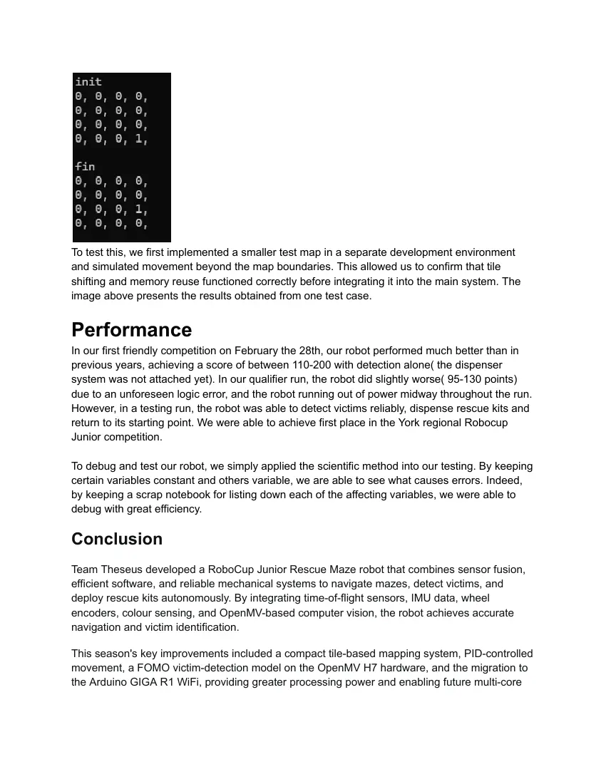
To test this, we first implemented a smaller test map in a separate development environment
and simulated movement beyond the map boundaries. This allowed us to confirm that tile
shifting and memory reuse functioned correctly before integrating it into the main system. The
image above presents the results obtained from one test case.
Performance
In our first friendly competition on February the 28th, our robot performed much better than in
previous years, achieving a score of between 110-200 with detection alone( the dispenser
system was not attached yet). In our qualifier run, the robot did slightly worse( 95-130 points)
due to an unforeseen logic error, and the robot running out of power midway throughout the run.
However, in a testing run, the robot was able to detect victims reliably, dispense rescue kits and
return to its starting point. We were able to achieve first place in the York regional Robocup
Junior competition.
To debug and test our robot, we simply applied the scientific method into our testing. By keeping
certain variables constant and others variable, we are able to see what causes errors. Indeed,
by keeping a scrap notebook for listing down each of the affecting variables, we were able to
debug with great efficiency.
Conclusion
Team Theseus developed a RoboCup Junior Rescue Maze robot that combines sensor fusion,
efficient software, and reliable mechanical systems to navigate mazes, detect victims, and
deploy rescue kits autonomously. By integrating time-of-flight sensors, IMU data, wheel
encoders, colour sensing, and OpenMV-based computer vision, the robot achieves accurate
navigation and victim identification.
This season's key improvements included a compact tile-based mapping system, PID-controlled
movement, a FOMO victim-detection model on the OpenMV H7 hardware, and the migration to
the Arduino GIGA R1 WiFi, providing greater processing power and enabling future multi-core
task separation. Competition and testing results showed significant improvement over previous
years while highlighting areas for further development.
Future work will focus on multi-floor navigation, improved obstacle traversal, faster victim
response, and further refinement of the robot's hardware and software to prepare for higher
levels of RoboCup competition.
24 pages, rendered as images so they load quickly. The text above is the document's own, extracted from the PDF.
Source code
The team's own source code, 25 KB. It is a download rather than part of this page, because a zip is something you open on your computer. It comes from GitHub, which some school networks block.