
Tachyons
Document register
- Poster1 pagePublished
- Presentation videoYouTubePublished
- Bill of materialsNot shared
- Team description paper10 pagesPublished
- Engineering journalNot shared
- Source codeNot shared
Sharing each document is the team's decision. “Not shared” means this team chose not to publish it, or did not submit one — not that it is missing from the archive.
In their words
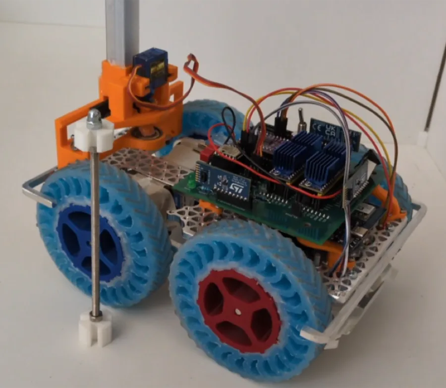
Q-Botto is a robot developed by the Tachyons team, its main objective since the beginning of the project was to develop and introduce new technologies to the rescuemaze competition, both for their educational value to the team’s members, and to differentiate the robot from other teams in the competition.
Its main chassis is CNC milled out of aluminum, it was designed by us and manufactured on a CNC lended by INFN LNS (the italian National Institute of Nuclear Physics National Laboratories of the South), and features a custom PCB, designed by us and manufactured by JLCPCB. The components were soldered by hand.
Its motors are Stepper motors driven by TMC2209 stepper drivers for high reliability and good performance.
The robot’s wheels are custom designed and Injection molded with silicone by us.
The suspensions are a type Christie suspension milled in aluminum in the same way as the chassis with some 3d printed parts for parts with more complex geometries
Poster
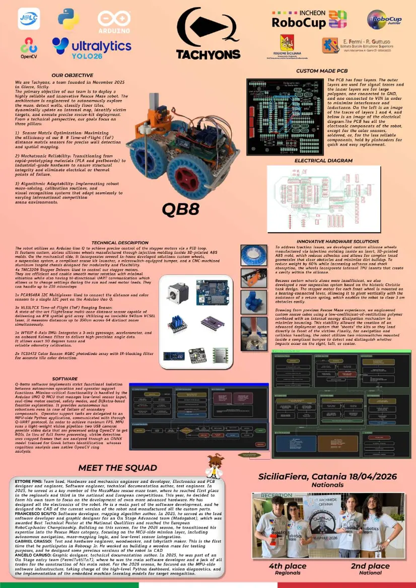
1 page, rendered as images so they load quickly. This document has no text layer — the words in it are part of the image.
Presentation video
Hosted on YouTube. The player loads only when you press play.
Team description paper
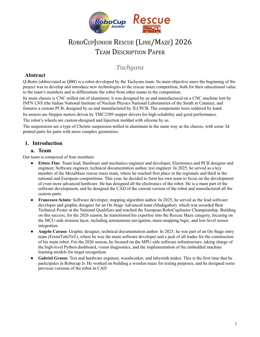
Show the remaining 7 pages
Read the text of this document — 4296 words
ROBOCUPJUNIOR RESCUE (LINE/MAZE) 2026
TEAM DESCRIPTION PAPER
Tachyons
Abstract
Q-Botto (abbreviated as QB8) is a robot developed by the Tachyons team. Its main objective since the beginning of the
project was to develop and introduce new technologies to the rescue maze competition, both for their educational value
to the team’s members and to differentiate the robot from other teams in the competition.
Its main chassis is CNC milled out of aluminum; it was designed by us and manufactured on a CNC machine lent by
INFN LNS (the Italian National Institute of Nuclear Physics National Laboratories of the South in Catania), and
features a custom PCB, designed by us and manufactured by JLCPCB. The components were soldered by hand.
Its motors are Stepper motors driven by TMC2209 stepper drivers for high reliability and good performance.
The robot’s wheels are custom-designed and Injection molded with silicone by us.
The suspensions are a type of Christie suspension milled in aluminum in the same way as the chassis, with some 3d
printed parts for parts with more complex geometries.
1. Introduction
a. Team
Our team is composed of four members:
● Ettore Fins: Team lead, Hardware and mechanics engineer and developer, Electronics and PCB designer and
engineer, Software engineer, technical documentation author, test engineer. In 2025, he served as a key
member of the MezaMaze rescue maze team, where he reached first place in the regionals and third in the
national and European competitions. This year, he decided to form his own team to focus on the development
of even more advanced hardware. He has designed all the electronics of the robot. He is a main part of the
software development, and he designed the CAD of the current version of the robot and manufactured all the
custom parts.
● Francesco Sciuto: Software developer, mapping algorithm author. In 2025, he served as the lead software
developer and graphic designer for an On Stage Advanced team (Madagabot), which was awarded Best
Technical Poster at the National Qualifiers and reached the European RoboCupJunior Championship. Building
on this success, for the 2026 season, he transitioned his expertise into the Rescue Maze category, focusing on
the MCU-side mission layer, including autonomous navigation, maze-mapping logic, and low-level sensor
integration.
● Angelo Caruso: Graphic designer, technical documentation author. In 2025, he was part of an On Stage entry
team (FermiTuttiTnT), where he was the main software developer and a jack of all trades for the construction
of his main robot. For the 2026 season, he focused on the MPU-side software infrastructure, taking charge of
the high-level Python dashboard, vision diagnostics, and the implementation of the embedded machine
learning models for target recognition.
● Gabriel Grasso: Test and hardware engineer, woodworker, and labyrinth maker. This is the first time that he
participates in Robocup Jr. He worked on building a wooden maze for testing purposes, and he designed some
previous versions of the robot in CAD
1
2. Project Planning
a. Overall Project Plan
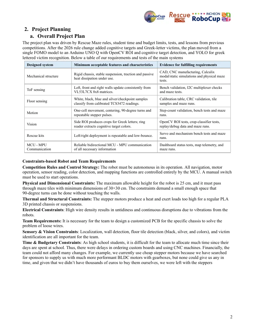
The project plan was driven by Rescue Maze rules, student time and budget limits, tests, and lessons from previous
competitions. After the 2026 rule change added cognitive targets and Greek-letter victims, the plan moved from a
single FOMO model to an Arduino UNO Q with OpenCV ROI and cognitive target detection, and YOLO for greek
lettered victim recognition. Below a table of our requirements and tests of the main systems
Designed system Minimum acceptable features and characteristics Evidence for fulfilling requirements
CAD, CNC manufacturing, Calculix
Rigid chassis, stable suspension, traction and passive
Mechanical structure modal/static simulations and physical maze
heat dissipation under use.
tests.
Left, front and right walls update consistently from Bench validation, I2C multiplexer checks
ToF sensing
VL53L7CX 8x8 matrices. and maze tests.
White, black, blue and silver/checkpoint samples Calibration table, CRC validation, tile
Floor sensing
classify from calibrated TCS3472 readings. samples and maze runs.
One-cell movement, centering, 90-degree turns and Step-count validation, bench tests and maze
Motion
repeatable stepper pulses. runs.
Side ROI produces crops for Greek letters; ring OpenCV ROI tests, crop-classifier tests,
Vision
reader extracts cognitive target colors. replay/debug data and maze runs.
Servo and mechanism bench tests and maze
Rescue kits Left/right deployment is repeatable and low-bounce.
runs.
MCU - MPU Reliable bidirectional MCU - MPU communication Dashboard status tests, map telemetry, and
Communication of all necessary information maze runs.
Constraints-based Robot and Team Requirements
Competition Rules and Control Strategy: The robot must be autonomous in its operation. All navigation, motor
operation, sensor reading, color detection, and mapping functions are controlled entirely by the MCU. A manual switch
must be used to start operations.
Physical and Dimensional Constraints: The maximum allowable height for the robot is 25 cm, and it must pass
through maze tiles with minimum dimensions of 30×30 cm. The constraints demand a small enough space that
90-degree turns can be done without touching the walls.
Thermal and Structural Constraints: The stepper motors produce a heat and exert loads too high for a regular PLA
3D printed chassis or suspensions.
Electrical Constraints: High wire density results in untidiness and continuous disruptions due to vibrations from the
robots.
Team Requirements: It is necessary for the team to design a customized PCB for the specific chassis to solve the
problem of loose wires.
Sensory & Vision Constraints: Localization, wall detection, floor tile detection (black, silver, and colors), and victim
identification are all important for the team.
Time & Budgetary Constraints: As high school students, it is difficult for the team to allocate much time since their
days are spent at school. Thus, there were delays in ordering custom boards and using CNC machines. Financially, the
team could not afford many changes. For example, we currently use cheap stepper motors because we have searched
for sponsors to supply us with much more performant BLDC motors with gearboxes, but none could give us any in
time, and given that we didn’t have thousands of euros to buy them ourselves, we were left with the steppers
2
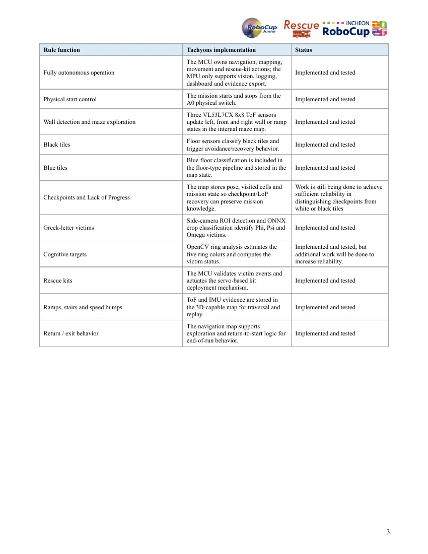
Rule function Tachyons implementation Status
The MCU owns navigation, mapping,
movement and rescue-kit actions; the
Fully autonomous operation Implemented and tested
MPU only supports vision, logging,
dashboard and evidence export.
The mission starts and stops from the
Physical start control Implemented and tested
A0 physical switch.
Three VL53L7CX 8x8 ToF sensors
Wall detection and maze exploration update left, front and right wall or ramp Implemented and tested
states in the internal maze map.
Floor sensors classify black tiles and
Black tiles Implemented and tested
trigger avoidance/recovery behavior.
Blue floor classification is included in
Blue tiles the floor-type pipeline and stored in the Implemented and tested
map state.
The map stores pose, visited cells and Work is still being done to achieve
mission state so checkpoint/LoP sufficient reliability in
Checkpoints and Lack of Progress
recovery can preserve mission distinguishing checkpoints from
knowledge. white or black tiles
Side-camera ROI detection and ONNX
Greek-letter victims crop classification identify Phi, Psi and Implemented and tested
Omega victims.
OpenCV ring analysis estimates the Implemented and tested, but
Cognitive targets five ring colors and computes the additional work will be done to
victim status. increase reliability.
The MCU validates victim events and
Rescue kits actuates the servo-based kit Implemented and tested
deployment mechanism.
ToF and IMU evidence are stored in
Ramps, stairs and speed bumps the 3D-capable map for traversal and Implemented and tested
replay.
The navigation map supports
Return / exit behavior exploration and return-to-start logic for Implemented and tested
end-of-run behavior.
3
b. Integration Plan
1. System Integration and Goal Attainment
For developing an efficient and entirely autonomous Robot, the team prioritized physical and electrical sturdiness prior
to software implementation. Functions such as maze mapping and vision were not implemented until the physical
hardware proved its validity.
The integration process hinged upon three pillars: tuning the 8×8 ToF matrices for accurate spatial mapping,
guaranteeing mechatronics through switching from PLA materials to industry-grade hardware, and flexibility of
algorithms for seamless adaptation to different competition floors.
2. Component Constraints and Fulfillment
All components were developed in accordance with constraints that stemmed from official rules of competitions:
Main Control Unit: Provides autonomous navigation, safety, motor control, sensor polling, map updates and rescue
actions without requiring the dashboard.
Robot Chassis: Designed in Autodesk Fusion 360 according to restrictions of height up to 25 cm and maximum
dimensions of 30x30 cm of a single tile, which allows 90-degree turns.
Aluminum Frame: The chassis, made of CNC-machined aluminum, was implemented to provide a structural passive
heat sink for the stepper motors.
Sensors: The ToF matrices were responsible for wall mapping with noise filtering libraries, while color sensors
recognized floor tiles based on CRC validation of calibration.
Custom PCB: Designed to achieve higher reliability and component density.
3. Internal Communication Architecture
The robot uses an MCU-centered architecture: the MCU owns mission decisions, while the MPU and Python
application provide vision assistance, logging, playback and operator visibility.
The internal communication architecture is bidirectional but authority is intentionally asymmetric: the MCU reports
state and accepts limited assistance messages, while the MPU cannot take over navigation.
Input: The MCU takes inputs from the ToF matrices through proprietary libraries and color sensors through CRC
checks.
Outputs and Diagnostics: The MCU communicates back with its internal map states and directs stepper motors to move
ahead with tiles, and in parallel, secondary MPU modules run vision diagnostics for ROI victims.
3. Hardware
The hardware of the robot consists of the mechanical structure and the electronics. The structure is centered around a
CNC-milled chassis. Above this main part, the PCB is held, with all the electronics except for the colour sensors, which
are held beneath the chassis in front of the front motors. Above the Main chassis, the rescue kit deployment system is
also held. It is an innovative design to shoot the cubes and make them hit the walls of the labyrinth without bouncing.
a. Mechanical Design and Manufacturing
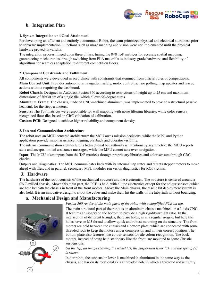
Fusion 360 render of the main parts of the robot with a simplified PCB on top.
The main structural part of the robot is an aluminum chassis machined on a 3 axis CNC.
It features an isogrid on the bottom to provide a high rigidity/weight ratio. In the
intersection of different triangles, there are holes, as in a regular isogrid, but here the
holes have an M3 thread to allow quick and robust mounting on the structure. The front
motors are held between the chassis and a bottom plate, which are connected with some
threaded rods to keep the motors under compression and in their correct position. The
bottom plate also features two colour sensors for tile colour recognition. The back
motors, instead of being held stationary like the front, are mounted to some Christie
suspensions.
On the left, an image showing the wheel (1), the suspension lever (3), and the spring (2)
is shown.
In our robot, the suspension lever is machined in aluminum in the same way as the
chassis, and has on its rotational axis a threaded hole in which a threaded rod is tightly
4
held, and which passes in some ball bearings held beneath the chassis to allow rotation. The spring is a tension spring,
and it applies a force to make the lever go down and keep the chassis at its desired height. The motor is connected
directly to the wheel and so moves up and down as well. The left and right suspensions are independent to allow
navigation on difficult terrain.
The wheels have been custom developed and injection molded by us, using regular transparent silicone caulk as the
material to provide low cost and high traction. As can be seen on the Fusion 360 render of the robot above, the wheels
are designed with an undulated surface, for higher traction on obstacles, and an airless design, for lower weight and
rotational inertia, and higher dampening to avoid passing great transient shocks to the motors. The hollow parts of the
wheel have some 3d printed TPU inserts, which have a much lower coefficient of restitution compared to the silicone,
allowing for wheels with low losses during nominal operation (e.g. rolling on even terrain), but with a lowered
coefficient of restitution on high loads, where the TPU parts experience high deformation. The wheels are molded with
a translucent PETG center, which can easily be put on the wheel supports (blue parts at the center of the wheels seen in
the Fusion 360 render above), for quick replacement in case of damage. The wheel supports are 3D printed in blue and
red PLA and have a screw to allow a firm connection to the motor's shaft.
The rescue kit deployment system is unlike any other that we have seen in competitions. It consists of a set of rails with
a slider held in the middle by two springs in tension pulling it on both sides. Pulling the slider to any side and releasing
it makes it accelerate very rapidly towards the center. A servo motor is mounted on the center of the side of the rails. It
rotates a compliant lever, which, when it reaches the center of the slider, has a pin that snaps into a channel in the slider.
Rotating the lever, it moves the slider until the pin uncatches, and the slider is released and goes back to the center. The
slider can house a Rescue kit on both sides of a central “bump”. Above the bump when the slider is centered, there is a
tower that holds up to 8 kits, one above the other. When the bump is moved, a kit falls to one side of it, where it is then
accelerated rapidly when the slider is released, allowing the cube to fly for about one meter. By rotating the lever to the
right, a kit is shot left, and by rotating the lever to the left, a kit is shot right.
Our rescue kits are not mere 3d printed PLA cubes, but instead engineered with minimizing the coefficient of
restitution as the main objective. They are mainly hollow with a wall thickness of about 0,8mm and a side length of
about 10mm. They are 3D printed with a filament selected for the lowest coefficient of restitution, in this case, a blue
TPU with unusual mechanical properties. On the inside, a mechanism is housed that dissipates
kinetic energy during impacts.
b. Electronic Design and Manufacturing
Our electronics design, like the hardware design, has the
objective of high reliability. To this end, we have designed
and manufactured (with JLCPCB) a custom PCB, Fusion 360
render below (note in the design of the pcb the components
used are not exactly the same as the ones soldered to the real
PCB because the correct part could not be found on publicly
available libraries easily, for example in the design, quartz
oscillators are placed instead of capacitors because the were
the only component we had the design on with the correct pin
spacing).
The PCB is a four-layered, so that the outer layers are used for
signal traces and the inner layers are for large polygons, one
connected to GND, and one connected to VIN in order to
minimize interference and inductance. On the left is an
image of the traces of layers 1 and 4, and on the right is an
image of the electrical diagram. The PCB has all the
electronic components of the robot, except for the color
sensors, soldered, or, for the less reliable components, held
by pinheaders for quick and easy replacement.
5
The main PCB components are:
● VL53L7CX, an 8*8 matrix ToF distance sensor that we chose for its wide FoV, and which was given to us by
STMicroelectronics.
● WT61P, an accelerometer and gyroscope that we chose for its precision and sensor fusion.
● TMC2209, a stepper motor driver that we chose for its low-vibration, operation, and UART communication,
which allows us to read the load the motors are subjected to and change the motor coil current and speed
accordingly.
● B32529C0564J000, film capacitors 560nf film capacitors for filtering and reducing noise on VIN.
● SW-T2-2E-A-A2-M1, switch for turning the robot on and off. In the render, it is the red switch.
● PCA9548A, the multiplexer for connecting all the I2C channels to a single I2C connection of the Arduino.
● Generic LEDs for indicating the status of the robot and identifying victims.
● Though not on the PCB, we have two TCS3472 colour sensors.
4. Software
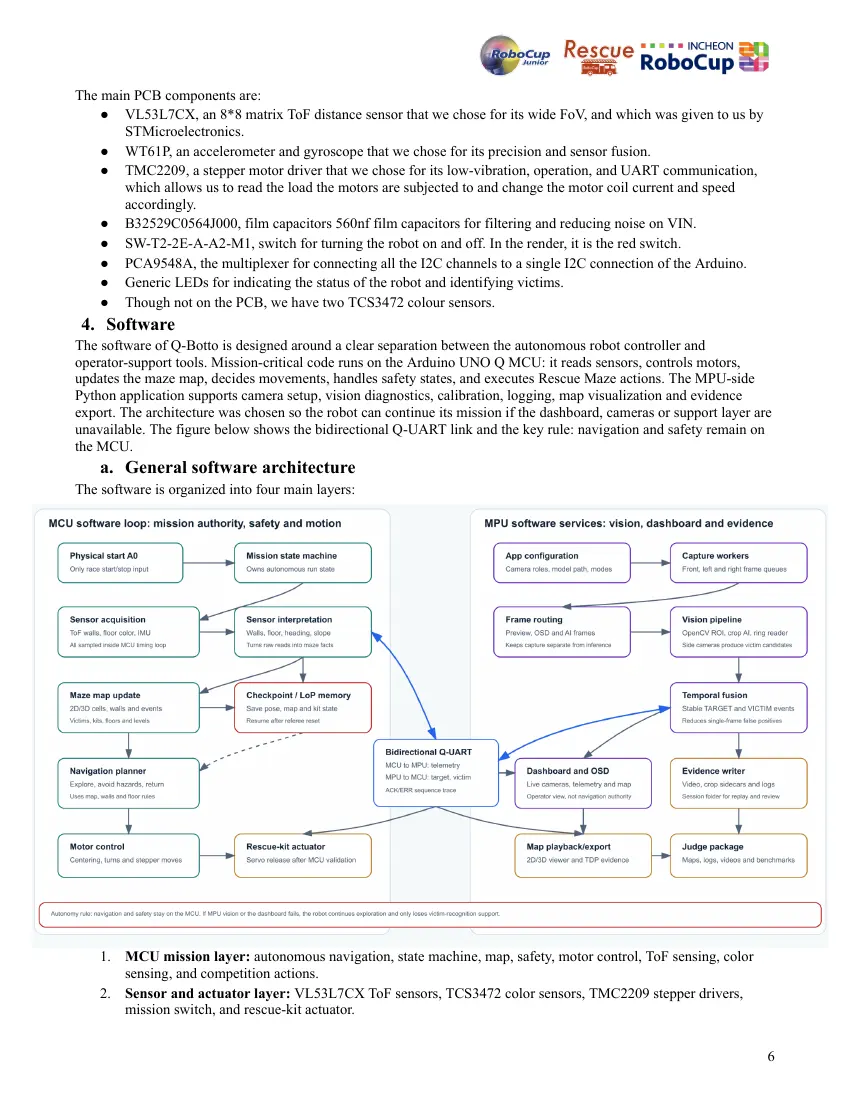
The software of Q-Botto is designed around a clear separation between the autonomous robot controller and
operator-support tools. Mission-critical code runs on the Arduino UNO Q MCU: it reads sensors, controls motors,
updates the maze map, decides movements, handles safety states, and executes Rescue Maze actions. The MPU-side
Python application supports camera setup, vision diagnostics, calibration, logging, map visualization and evidence
export. The architecture was chosen so the robot can continue its mission if the dashboard, cameras or support layer are
unavailable. The figure below shows the bidirectional Q-UART link and the key rule: navigation and safety remain on
the MCU.
a. General software architecture
The software is organized into four main layers:
1. MCU mission layer: autonomous navigation, state machine, map, safety, motor control, ToF sensing, color
sensing, and competition actions.
2. Sensor and actuator layer: VL53L7CX ToF sensors, TCS3472 color sensors, TMC2209 stepper drivers,
mission switch, and rescue-kit actuator.
6
3. MPU support layer: Python dashboard, calibration tools, camera setup, video/log playback, and map
visualization.
4. Vision support layer: side-camera target diagnostics using OpenCV ROI detection, an ONNX crop classifier
for Greek-letter victims, and OpenCV ring analysis for cognitive targets.
The MCU software is structured around robot concepts rather than generic infrastructure. The main concepts are: robot
pose, heading, cell, walls, floor type, map, navigation decision, motor command, and mission state. The mission starts
from a physical input from the switch connected to A0. When the input is HIGH, the robot starts or continues the
autonomous mission. When the input is LOW, the mission is reset and the motors are disabled.
The map is a compact grid of cells. Each cell stores its coordinates, level, floor type, wall state, target mask, visit count,
and other mission flags. When the robot enters a cell, it marks the cell as visited. When it reads the ToF sensors, it
updates the left, front, and right wall states. The wall updates are symmetric, so if one cell records a wall or opening,
the neighboring cell is updated consistently.
The navigation algorithm currently follows a frontier-exploration strategy. It first tries to move forward, then left, then
right, if the neighboring cell is open and unvisited. If all immediate neighbors are already visited or blocked, it uses a
Dijkstra-style search on the visited map to find the nearest cell that still borders an unexplored frontier. This gives the
robot a basic exploration and backtracking behavior without storing a large map.
The motor layer uses stepper motors driven by TMC2209 drivers. The MCU generates timed step pulses with
acceleration ramps and tracks travelled distance through step counts. The robot is designed to move one cell at a time,
in software, though in practice it moves fluidly and continuously, and only turns after it has stopped at the center of the
current cell.
The sensor layer reads three VL53L7CX 8x8 ToF sensors through an I2C multiplexer. The raw matrix is reduced to
distance values for the left, front, and right sides and wall inclination, used for PID motion, centering, and ramp
recognition. Color is detected with two TCS3472 sensors mounted under the robot. The software compares normalized
RGBC values against calibrated samples for white, black, blue, silver/checkpoint, and red tiles.
The Python support software provides a local dashboard. It shows mission state, sensor status, map state, camera views,
calibration tools, and playback evidence. The dashboard can send color calibration data to the MCU through compact
RouterBridge messages. It can also receive target events from the vision system, but the MCU remains responsible for
the autonomous mission.
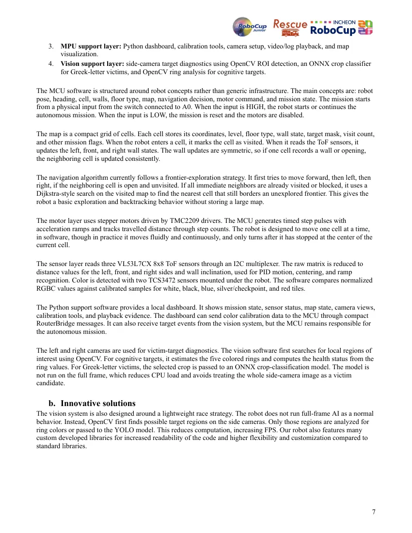
The left and right cameras are used for victim-target diagnostics. The vision software first searches for local regions of
interest using OpenCV. For cognitive targets, it estimates the five colored rings and computes the health status from the
ring values. For Greek-letter victims, the selected crop is passed to an ONNX crop-classification model. The model is
not run on the full frame, which reduces CPU load and avoids treating the whole side-camera image as a victim
candidate.
b. Innovative solutions
The vision system is also designed around a lightweight race strategy. The robot does not run full-frame AI as a normal
behavior. Instead, OpenCV first finds possible target regions on the side cameras. Only those regions are analyzed for
ring colors or passed to the YOLO model. This reduces computation, increasing FPS. Our robot also features many
custom developed libraries for increased readability of the code and higher flexibility and customization compared to
standard libraries.
7
5. Performance evaluation
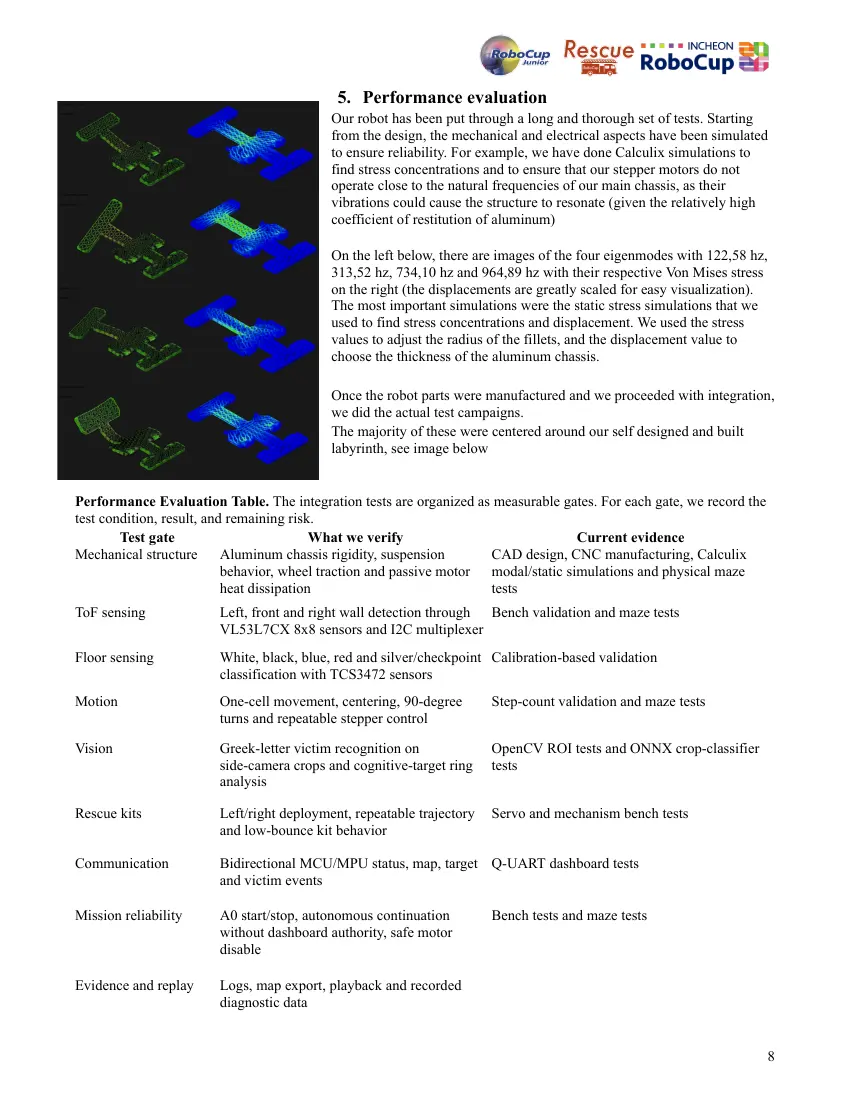
Our robot has been put through a long and thorough set of tests. Starting
from the design, the mechanical and electrical aspects have been simulated
to ensure reliability. For example, we have done Calculix simulations to
find stress concentrations and to ensure that our stepper motors do not
operate close to the natural frequencies of our main chassis, as their
vibrations could cause the structure to resonate (given the relatively high
coefficient of restitution of aluminum)
On the left below, there are images of the four eigenmodes with 122,58 hz,
313,52 hz, 734,10 hz and 964,89 hz with their respective Von Mises stress
on the right (the displacements are greatly scaled for easy visualization).
The most important simulations were the static stress simulations that we
used to find stress concentrations and displacement. We used the stress
values to adjust the radius of the fillets, and the displacement value to
choose the thickness of the aluminum chassis.
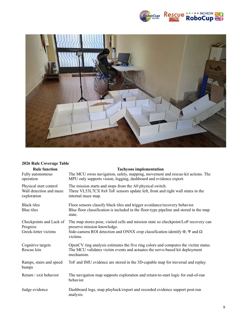
Once the robot parts were manufactured and we proceeded with integration,
we did the actual test campaigns.
The majority of these were centered around our self designed and built
labyrinth, see image below
Performance Evaluation Table. The integration tests are organized as measurable gates. For each gate, we record the
test condition, result, and remaining risk.
Test gate What we verify Current evidence
Mechanical structure Aluminum chassis rigidity, suspension CAD design, CNC manufacturing, Calculix
behavior, wheel traction and passive motor modal/static simulations and physical maze
heat dissipation tests
ToF sensing Left, front and right wall detection through Bench validation and maze tests
VL53L7CX 8x8 sensors and I2C multiplexer
Floor sensing White, black, blue, red and silver/checkpoint Calibration-based validation
classification with TCS3472 sensors
Motion One-cell movement, centering, 90-degree Step-count validation and maze tests
turns and repeatable stepper control
Vision Greek-letter victim recognition on OpenCV ROI tests and ONNX crop-classifier
side-camera crops and cognitive-target ring tests
analysis
Rescue kits Left/right deployment, repeatable trajectory Servo and mechanism bench tests
and low-bounce kit behavior
Communication Bidirectional MCU/MPU status, map, target Q-UART dashboard tests
and victim events
Mission reliability A0 start/stop, autonomous continuation Bench tests and maze tests
without dashboard authority, safe motor
disable
Evidence and replay Logs, map export, playback and recorded
diagnostic data
8
2026 Rule Coverage Table
Rule function Tachyons implementation
Fully autonomous The MCU owns navigation, safety, mapping, movement and rescue-kit actions. The
operation MPU only supports vision, logging, dashboard and evidence export.
Physical start control The mission starts and stops from the A0 physical switch.
Wall detection and maze Three VL53L7CX 8x8 ToF sensors update left, front and right wall states in the
exploration internal maze map.
Black tiles Floor sensors classify black tiles and trigger avoidance/recovery behavior.
Blue tiles Blue floor classification is included in the floor-type pipeline and stored in the map
state.
Checkpoints and Lack of The map stores pose, visited cells and mission state so checkpoint/LoP recovery can
Progress preserve mission knowledge.
Greek-letter victims Side-camera ROI detection and ONNX crop classification identify Φ, Ψ and Ω
victims.
Cognitive targets OpenCV ring analysis estimates the five ring colors and computes the victim status.
Rescue kits The MCU validates victim events and actuates the servo-based kit deployment
mechanism.
Ramps, stairs and speed ToF and IMU evidence are stored in the 3D-capable map for traversal and replay.
bumps
Return / exit behavior The navigation map supports exploration and return-to-start logic for end-of-run
behavior.
Judge evidence Dashboard logs, map playback/export and recorded evidence support post-run
analysis.
9
6. Conclusion
The creation of Q-Botto by the Tachyons team was a meticulously integrated and designed hardware-software solution
that was tailored to meet the specific physical and algorithmic challenges of the RoboCupJunior Rescue Maze
competition. With the implementation of a 3-axis CNC milled aluminum chassis, which had been validated through
Calculix modal and static stress simulation models, an optimal ratio of rigidity-to-weight was established, while the
problem of thermal constraints presented by the hot stepper motors driven by the TMC2209 controller was solved by
using the chassis as an efficient passive heatsink.
In terms of software and electronics, the electrical integration was made possible by our custom 4-layer PCB design
that permitted a reliable, robust, and compact design. The MCU of the Arduino UNO was able to perform all the
algorithms, sensor and motor controls, while communicating with the MPU for victim recognition. Through
computation offloading through the use of efficient vision techniques involving the application of OpenCV region of
interest (ROI) filtering before activation of the YOLO algorithm, the robot is able to maintain a high frame rate while
identifying cognitive targets efficiently and effectively. Our thorough testing inside our proprietary physical testing
maze system proves that we have addressed the past regional failure issues in terms of regional-stage execution.
Overall, the creation of Q-Botto not only meets all the challenging autonomy criteria but is also a powerful learning
pipeline in practicing engineering principles.
10
10 pages, rendered as images so they load quickly. The text above is the document's own, extracted from the PDF.