
Pi-rates
Document register
- Poster1 pagePublished
- Presentation videoYouTubePublished
- Bill of materials87 KBPublished
- Team description paper10 pagesPublished
- Engineering journalNot shared
- Source code14 KB · GitHubPublished
Sharing each document is the team's decision. “Not shared” means this team chose not to publish it, or did not submit one — not that it is missing from the archive.
In their words
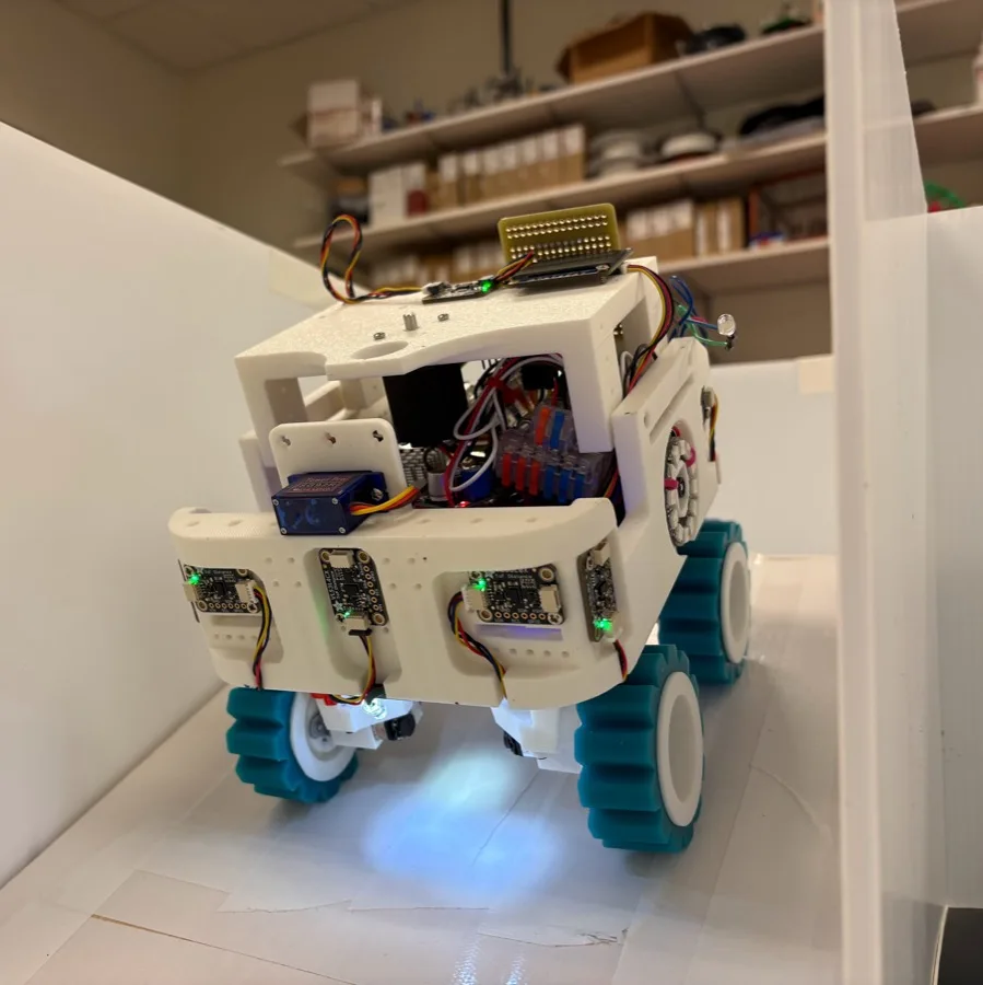
We are the Pi-rates from Branchburg, New Jersey. Our robot is created by using different actuators, sensors, and microcontrollers, packed into a 3D-printed chassis. Actuators on the robot include geared metal motors for drive and a combination of a stepper motor and a servo, which are used to deliver rescue kits to victims in the maze. Some sensors of the Pi-rates team robot include time-of-flight, encoders, IMU sensors, and wide-angle Raspberry Pi cameras. Along with the actuators and sensors, the robot uses a Pico and a Raspberry Pi 5 to process sensor inputs and generate navigation outputs. Our robot is capable of traversing the maze, identifying victims, avoiding obstacles, and dropping rescue kits along the way. After visiting every tile, the robot is able to traverse back to the point of origin. Some capabilities that set our team apart from competitors are how we handle challenges such as alignment and weight distribution. Members of our team have past knowledge in different aspects of robotics, which gave us the capability to refine our hardware and software.
Poster
Read the text of this document — 640 words
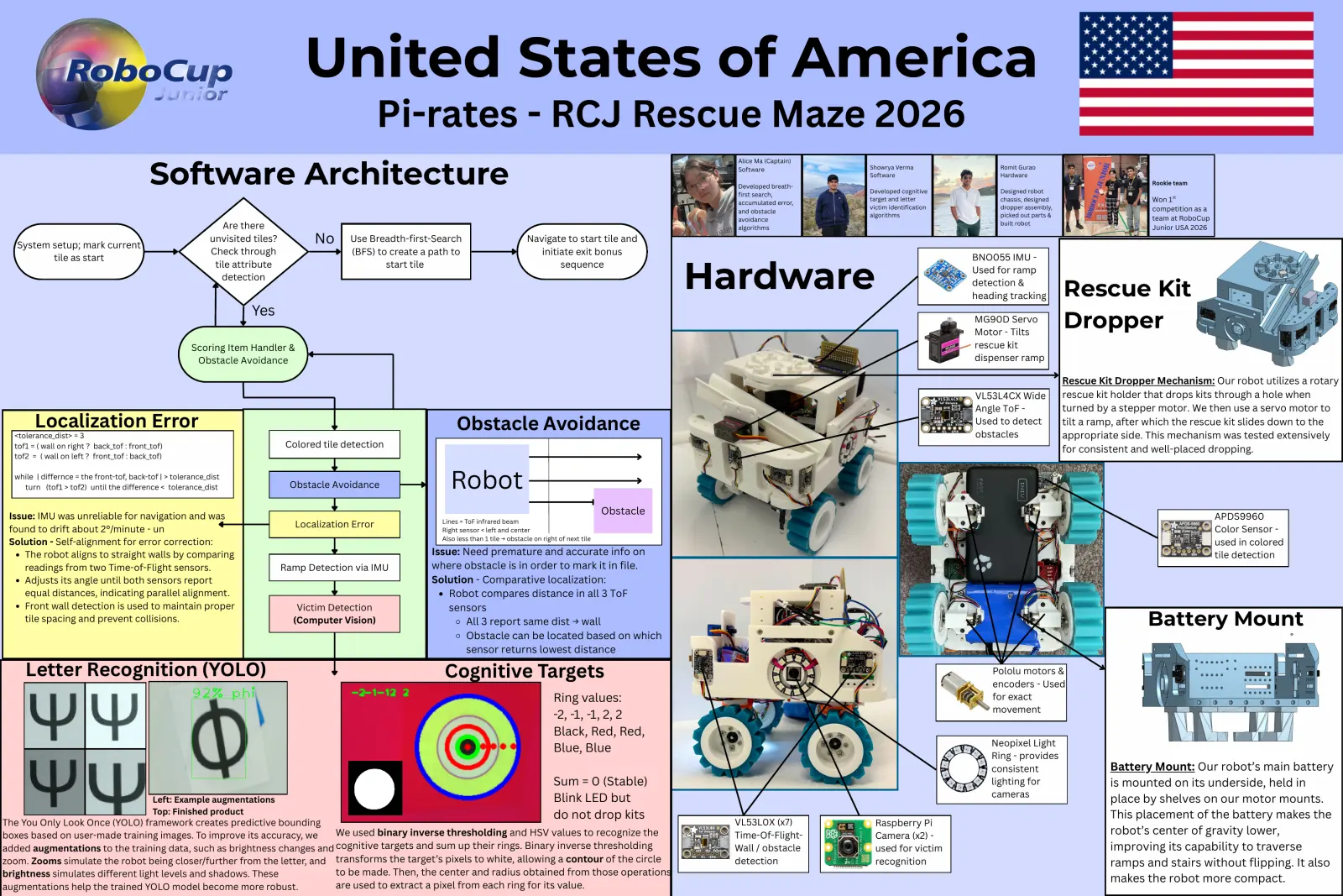
United States of America
Pi-rates - RCJ Rescue Maze 2026
Software Architecture
Alice Ma (Captain)
Software Showrya Verma Romit Gurao
Software Hardware
Rookie team
Developed breath-
Developed cognitive Designed robot
first search,
accumulated error,
target and letter chassis, designed Won 1st
victim identification dropper assembly, competition as a
and obstacle
algorithms picked out parts &
avoidance team at RoboCup
Are there algorithms
built robot
Junior USA 2026
System setup; mark current
unvisited tiles? No Use Breadth-first-Search Navigate to start tile and
Check through (BFS) to create a path to initiate exit bonus
tile as start BNO055 IMU -
Hardware
tile attribute start tile sequence
Used for ramp
detection
detection &
heading tracking Rescue Kit
Yes MG90D Servo
Motor - Tilts
Dropper
Scoring Item Handler & rescue kit
Obstacle Avoidance dispenser ramp
Rescue Kit Dropper Mechanism: Our robot utilizes a rotary
VL53L4CX Wide rescue kit holder that drops kits through a hole when
Angle ToF - turned by a stepper motor. We then use a servo motor to
Localization Error Obstacle Avoidance Used to detect tilt a ramp, after which the rescue kit slides down to the
<tolerance_dist> = 3 obstacles appropriate side. This mechanism was tested extensively
tof1 = ( wall on right ? back_tof : front_tof) Colored tile detection
for consistent and well-placed dropping.
tof2 = ( wall on left ? front_tof : back_tof)
while | differnce = the front-tof, back-tof | > tolerance_dist
turn (tof1 > tof2) until the difference < tolerance_dist Obstacle Avoidance Robot
Issue: IMU was unreliable for navigation and was
Obstacle
Lines = ToF infrared beam
APDS9960
found to drift about 2°/minute - un Localization Error
Right sensor < left and center Color Sensor -
Also less than 1 tile → obstacle on right of next tile
Solution - Self-alignment for error correction: used in colored
The robot aligns to straight walls by comparing Issue: Need premature and accurate info on tile detection
readings from two Time-of-Flight sensors. Ramp Detection via IMU where obstacle is in order to mark it in file.
Oukeda NEMA-8
Adjusts its angle until both sensors report Solution - Comparative localization:
Stepper Motor-
equal distances, indicating parallel alignment. Robot compares distance in all 3 ToF
Turns rescue kit
Front wall detection is used to maintain proper Victim Detection sensors
tile spacing and prevent collisions. (Computer Vision) All 3 report same dist → wall
holder
Battery Mount
Obstacle can be located based on which
sensor returns lowest distance
Letter Recognition (YOLO) Cognitive Targets Pololu motors &
encoders - Used
Ring values: for exact
movement
-2, -1, -1, 2, 2
Black, Red, Red,
Neopixel Light
Blue, Blue
Ring - provides
consistent Battery Mount: Our robot’s main battery
Sum = 0 (Stable) lighting for is mounted on its underside, held in
Blink LED but cameras
Left: Example augmentations place by shelves on our motor mounts.
Top: Finished product do not drop kits This placement of the battery makes the
The You Only Look Once (YOLO) framework creates predictive bounding VL53L0X (x7) Raspberry Pi
boxes based on user-made training images. To improve its accuracy, we We used binary inverse thresholding and HSV values to recognize the Time-Of-Flight- Camera (x2) - robot’s center of gravity lower,
added augmentations to the training data, such as brightness changes and cognitive targets and sum up their rings. Binary inverse thresholding Wall / obstacle used for victim improving its capability to traverse
zoom. Zooms simulate the robot being closer/further from the letter, and transforms the target’s pixels to white, allowing a contour of the circle detection recognition ramps and stairs without flipping. It also
brightness simulates different light levels and shadows. These to be made. Then, the center and radius obtained from those operations
makes the robot more compact.
augmentations help the trained YOLO model become more robust. are used to extract a pixel from each ring for its value.
1 page, rendered as images so they load quickly. The text above is the document's own, extracted from the PDF.
Presentation video
Hosted on YouTube. The player loads only when you press play.
Bill of materials
Shown as the original PDF, because this one is smaller that way and its text stays selectable and searchable.
Team description paper
Show the remaining 7 pages
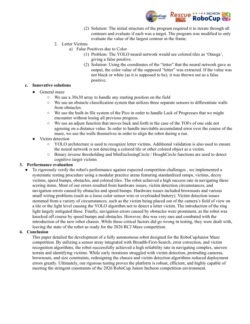
Read the text of this document — 4832 words
ROBOCUPJUNIOR RESCUE MAZE 2026
TEAM DESCRIPTION PAPER
Pi-rates
Abstract
We are the Pi-rates from Branchburg, New Jersey. Our robot is created by using different actuators,
sensors, and microcontrollers, packed into a 3D-printed chassis. Actuators on the robot include geared
metal motors for drive and a combination of a stepper motor and a servo, which are used to deliver rescue
kits to victims in the maze. Some sensors of the Pi-rates team robot include time-of-flight, encoders, IMU
sensors, and wide-angle Raspberry Pi cameras. Along with the actuators and sensors, the robot uses a Pico
and a Raspberry Pi 5 to process sensor inputs and generate navigation outputs. Our robot is capable of
traversing the maze, identifying victims, avoiding obstacles, and dropping rescue kits along the way. After
visiting every tile, the robot is able to traverse back to the point of origin. Some capabilities that set our
team apart from competitors are how we handle challenges such as alignment and weight distribution.
Members of our team have past knowledge in different aspects of robotics, which gave us the capability to
refine our hardware and software.
Introduction
1. Team
● Alice Ma is currently a 9th grader at Hillsborough High School. She wrote the code for the RP2350, which
is responsible for traversing the maze by interpreting sensor values and handling camera values for
victims. She also assisted in the technical design of the robot and the integration of the CV and Arduino
code. Her past experiences include: 1st overall at RoboCup Jr. Rescue Line Primary Nationals.
● Romit Gurao is currently an 8th grader at Mount Olive Middle School in Morris County, New Jersey. He
worked on the hardware and electronics aspects of the robot. Along with electronics, Romit has also
contributed to the CAD assembly of his team's robot, mainly working in the OnShape platform. His past
experiences include: FLL competitions in 2023 and 2024, FTC Mechanical Lead MORT Jr, and the
Congressional App Challenge 2025/2026.
● Showrya Verma is currently a 9th grader at Bridgewater-Raritan High School. He handled the computer
vision aspect, including building algorithms for analyzing cognitive targets and implementing the You
Only Look Once software for letter recognition. His past experiences include: 2nd overall at RoboCup Jr.
Rescue Line Primary USA (2023) and American Computer Science League finals (2026).
Project Planning
a. Overall Project Plan
● Our Team’s Objective
○ Our objective for RoboCup Junior Rescue Maze is to design a fully autonomous robot capable of
efficiently navigating a maze environment while also performing tasks such as wall tracing,
obstacle avoidance, ramp/stairs, colored tile detection, victim identification, and bullseye, while
maintaining stability and accuracy under time constraints.
● Requirements and Constraints
○ Physical constraints: compact chassis capable of fitting within the maze, stable maneuvering over
ramps, stairs, and uneven floor, must integrate multiple sensors (LiDAR/Time-of-Flight, cameras,
IMU (Gyroscope), etc.), and limited space for electronics (Pi 5, Cytron/Pico controller, batteries)
1
○ Competition constraints: fully autonomous operation, detection and response to victims and
markers, accurate navigation through maze sections, and reliable obstacle detection and avoidance
without human intervention
● Milestones
Date Milestone Lead(s)
January 5 ● Breadth-First-Search-based autonomous navigation Alice
○ Integrated wall detection using Time-Of-Flight
sensor feedback
○ Added visited-state tracking, backtracking, and
return-to-start functionality
January 13 ● 3D printed chassis capable of maze travel Romit
○ Optimized weight distribution (low center of
gravity via bottom battery placement)
○ Implemented silicone tires and a 4-motor encoder
drive for stability on ramps/stairs/speed bumps
February 16 Rescue kit deployment system including stepper-driven dispensing Romit
wheel for controlled kit release, servo-controlled ramp for
directional placement, and fully modular dropper assembly for
maintenance and testing
February 20 ● Vision system (YOLO, cognitive targets, letters) Showrya
○ Dual Raspberry Pi camera integration
○ YOLO model pipeline for detection tasks
○ Bullseye detection using contour and threshold
pipeline
March 9 ● Colored tile integration into navigation Alice
○ RGB/threshold-based detection for tile
classification
○ Integrated tile effects into BFS decision logic
○ Adjusted traversal behavior based on tile type
May 5 ● Obstacle detection and avoidance integration Alice
○ ToF (Time of Flight) and LiDAR-based obstacle
detection system
○ State-based avoidance behavior integrated into
navigation loop
○ Dynamic path adjustment within BFS framework
May 10 ● Full autonomous system integration Alice, Showrya
○ Combined BFS, vision, sensors
○ Enabled full maze traversal under competition
constraints
○ Integrated colored tiles, obstacles, victims, and
rescue kit dropping using cameras
● Planning Strategy
○ Tasks divided into subsystems: mechanical, navigation, sensors, vision, and integration
○ Milestones completed in the order of dependency:
● mechanical -> movement -> BFS -> sensors -> vision -> full integration
○ Mechanical and movement were prioritized first to ensure reliable movement before logic.
○ CV, BFS, and hardware were worked on simultaneously to save time
○ Testing was performed after each milestone and used iterative debugging
b. Integration Plan
● System distributes tasks:
○ Raspberry Pi 5 is used for vision processing and navigation
○ Pico/Cytron is used for motor and sensor control
● Communication:
○ Serial communication between the Pi and the controller
○ Sensors & ToFs feed data to Cytron, used for movement and BFS
○ Cameras feed image data to the Pi, used for victim detection
● Component Integration:
○ Navigation (BFS) - controls movement and path planning
○ Sensors (ToF, IMU, LiDAR, color) - provide wall, obstacle, and tile information
○ Vision (YOLO, CV) - detects victims and targets
○ Encoders - ensure accurate movement and turning
○ Rescue system - triggered based on stimulus
Hardware
1. Our robot has a chassis mainly composed of 3D printed parts using PLA material, with a double-decker design
for optimal use of component placement.
2. There are many sensors on our robot, including: 2 Raspberry Pi Cameras, a color sensor, a LiDAR sensor, 6
time of flight sensors, and a gyroscopic sensor.
3. All of the I2C sensors are connected to a Multiplexer (MUX).
4. We use 4 micro metal gear motors to control the wheels and robot movement.
5. We use a stepper motor and a servo motor to control the rescue kit mechanism.
6. Our robot uses custom-created silicone tires that fit a 3D printed rim which is attached to purchased motors
c. Mechanical Design and Manufacturing
● Mechanical Design
i. Chassis
1. Our robot chassis layers the heaviest items at the bottom and lighter items at the top.
The batteries are positioned at the base of the chassis to achieve a low center of
gravity, significantly improving stability and preventing the robot from toppling. Our
team used custom created silicone wheels for better grip of ramps and stairs, and to
effectively cross speed bumps. The design of the chassis consists of a rectangular
body with multiple openings for wiring and accessibility, as well as holes for
mounting all sensors and other components. A rescue kit dropper assembly is attached
to the main structure at the top
ii. Drive System & Wheels
1. Four micro metal gear motors with encoders are used for movement of the robot
because encoders provide precise movement
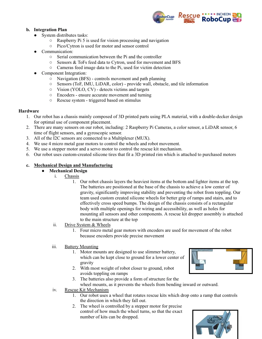
iii. Battery Mounting
1. Motor mounts are designed to use slimmer battery,
which can be kept close to ground for a lower center of
gravity
2. With most weight of robot closer to ground, robot
avoids toppling on ramps
3. The batteries also provide a form of structure for the
wheel mounts, as it prevents the wheels from bending inward or outward.
iv. Rescue Kit Mechanism
1. Our robot uses a wheel that rotates rescue kits which drop onto a ramp that controls
the direction in which they fall out.
2. The wheel is controlled by a stepper motor for precise
control of how much the wheel turns, so that the exact
number of kits can be dropped.
3. The ramp is turned by the servo motor to control the direction in which the rescue kits
slide off the robot.
4. Rescue kit holder assembly holds moving components, these components can be
easily attached/detached to the robot with the use of four screws
a. Allows accessibility of inner components/wiring.
v. Camera mounting
1. To keep protruding cameras from colliding with external objects, cameras are
mounted to an alcove on the inside face of the robot chassis's walls.
a. These alcoves ensure the camera lens is flush with the external surface of the
chassis wall, preventing collision with external factors.
b. Also, neopixel ring holders are mounted to the outside of the robot in an
indent
i. These illuminate the walls surrounding the camera, providing lighting
consistency for victim detection.
● Manufacturing
I. Three main manufactured parts of the robot are chassis, mounts for components, and wheels
II. Chassis of robot is modeled using Onshape and SketchUp online CAD platforms
III. Majority of the robot chassis and mounts are 3D printed with PLA plastic
IV. All major electronics parts and components such as motors,sensors,actuators, and
microcontrollers are purchased from vendors such as Adafruit and Pololu
V. Wheels manufactured by following method
A. Shape of wheel is created in CAD
B. The wheel shape is hollowed out to create a mold specifically for the tire.
C. A cylindrical core is then extruded within this wheel-shaped void.
D. Once mold model is created, it is 3D printed
E. Silicone mixture is poured into mould and left to thicken
F. Once mixture is thickened, the tire is taken out of the mold and rim is 3D printed to fit
the tire
G. Wheel and rim are attached to the micro metal gear motor using adapter
vi. Testing Procedures
1. To test the mechanical functionality of the robot, we used several tests:
a. Ramp: The robot is sent up and down a 5-foot, 25-degree inclined plane with
weights on both front and back to see if it can handle ramps steadily.
b. Stairs: Tiles are stacked to create a 60 cm set of stairs that increase and
decrease the robot’s altitude. Weights are added to the robot to further test its
capabilities.
c. Speed Bump: The robot is sent over varying heights, orientations, and sizes of
speed bumps to see if the robot can stay on course despite them. Motor speeds
are tweaked based on results.
d. Point Turn: The robot spins all four motors at the same speed (left side and
right side in different directions). From this test, we can gather if the wheels
are drifting, if voltage is adequate, and if wheels are aligned.
● Problems and solutions
vii. Problem: Drift during point turns causes an inaccurate final position
1. Although we used the IMU for accurate turns, the wheels were slipping, causing the
robot to be off-center and land in a different position than when it started, even though
it was facing the right direction.
2. To address this issue, we utilized the encoders on our wheels, which ensured both left
and right sides rotate the exact same amount during point turns. This prevented one
side from overpowering the other, allowing the robot to self-correct during rotation
and maintain a centered final position in the maze.
3. Along with utilizing encoders, we learned that the current wheel attachment method
did not always result in a fixed axis, and the axis of rotation would wobble during
motor spin. After reattaching and aligning the wheels, the
robot could make sharper point turns
viii. Problem: Robot toppling in more complex maneuvering
1. In our original design for the robot, the robot would fall
either forward or backward on the ramp.
2. To address this, instead of keeping the batteries at the
same level as the rest of the components higher up, we
modified the wheel mounts to create room for the batteries
(our heaviest components) at the bottom of the robot. This
significantly lowered the center of mass on the robot, and kept it
stable on inclines.
3. Instead of using one battery pack, two battery packs are utilized to
add weight to both front and back of the robot, this ensures that
while ascending or descending on ramps wheels are always touching table
4. Utilizing the IMU when elevation was detected the robot adjusts speed to ensure
toppling is avoided
ix. Problem: Difficult access to internal components during testing and repairs.
1. Our original design had a rigid roof, making it increasingly difficult to wire new
sensors or modify our hardware that were inside of the robot.
2. To fix this issue, we adjusted our chassis design to be modular, with openings and a
detachable rescue kit assembly (roof) secured by just four screws for quick removal.
x. Problem:In first version of robot, many components were sticking outside of the robot, due to
this robot was getting stuck on walls, and wires were easy to disconnect
1. Chassis was redesigned with indents along the chassis wall which protected all sensors
from colliding with walls
2. MUX(device that connects all sensors) of robot was put underneath the robot in order
to make wiring and connections to sensors easier, decreasing risk of unplugged wires
Electronic Design and Manufacturing
2. Electric components
i. Time-Of-Flight sensors (VL53LOX)
1. Infrared light is excreted and time it takes to receive signal is calculated
2. Time of flight sensors distance helps robot determine walls and obstacles in maze
3. 6 sensors are used on bot, and sensors are wired to Multiplexer using stemma
connection
ii. IMU Gyro (BNO055)
1. Uses a 9-axis magnetometer to detect angles of three directional rotation
2. IMU is used to accurately navigate in maze
3. IMU helps determine if the robot is on ramps or stairs, which can then adjust wheel
speed
iii. Wide View Time-Of-Flight (VL53L4CX)
1. Our team has utilized time-of-flight sensors to return readings from a larger field of
view
2. The VL53LCX is a singular sensor mounted in the central front part of the robot
3. This sensor is a Time Of Flight sensors that has greater range, and can return the
lengths of different objects in its path of view
4. Obstacle detection is done using this sensor
5. Sensor is connected to main robot with multiplexer (MUX)
iv. Color Sensor (APDS-9960)
1. Our team has utilized a RGB color sensor to detect colored tiles within the maze
2. Singular sensor is mounted beneath the front part of robot
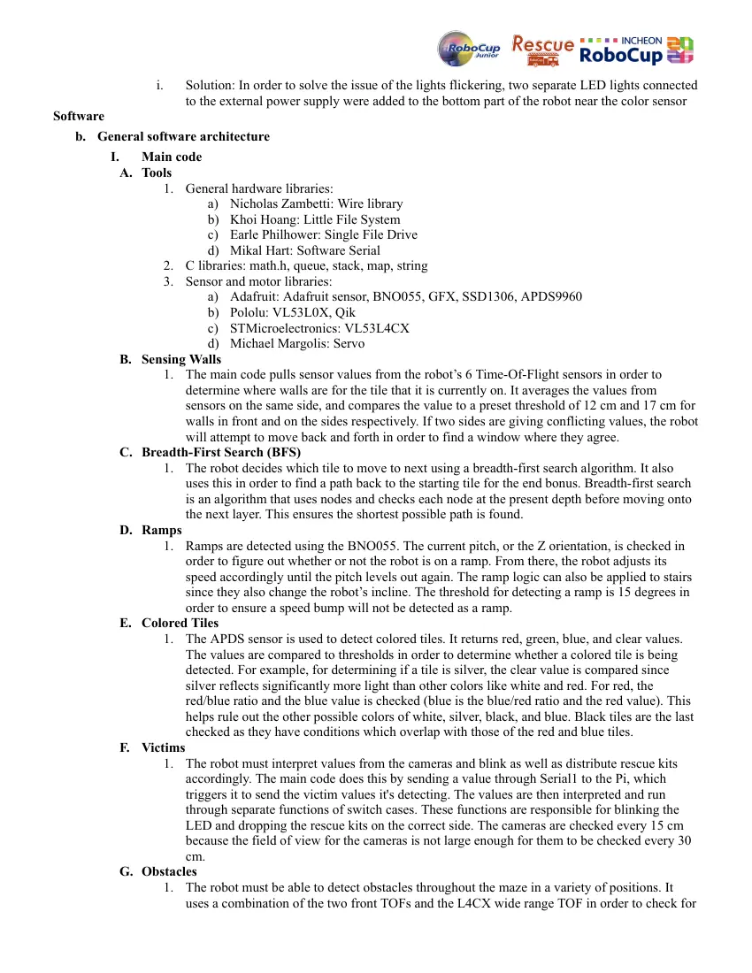
v. Pololu Qik 2s12v10 motor controller
1. Our robot utilizes motor controllers to provide
voltage to four motors
2. Motor controllers communicate with pico using
serial, on pico GPIO pins do motor control
3. Main power supply is hooked up to Motor
controller and then distributed to Pico, and 5V
components
vi. Pololu Micro Metal Geared motors- used for movement
vii. OLED display
viii. Servo
ix. Raspberry Pi 5: used for running OpenCV and vision
libraries and connected to Pico using serial communication
x. Pico: used for controlling motors and sensors of robot and uses RP2040 cpu chip
Innovative solutions
a. Problem: Previously, our team was using a Cytron Motion Pro 2350 to control the entire robot. With
the addition of many sensors and components over time, the Cytron’s output voltage draw exceeded its
capacity. Excessive output voltage caused a pin on the CPU to pull up when motors were under stress
(such as turns and ramps). Two solutions were to add a motor controller or use a more powerful
battery. Using a more powerful battery, however, would add size and weight.
i. Solution: To solve the brownout and power issue on our robot, we decided that it was best to
use a motor controller. A motor controller has many advantages and disadvantages. With an
external motor controller, more GPIO pins would have to be used. However, the Cytron
Motion Pro did not have enough pins to accommodate the motor controller. In order to use the
motor controllers we decided to use a Pico 2, which gave us more wiring flexibility, and
freedom wiring components.
b. Problem:Using a MUX to connect more than 9 stemma components puts voltage strain on certain
components. Due to the strain on voltage, an in built light on our robots color sensor is not able to get
stable values as color sensor light flickers
i. Solution: In order to solve the issue of the lights flickering, two separate LED lights connected
to the external power supply were added to the bottom part of the robot near the color sensor
Software
b. General software architecture
I. Main code
A. Tools
1. General hardware libraries:
a) Nicholas Zambetti: Wire library
b) Khoi Hoang: Little File System
c) Earle Philhower: Single File Drive
d) Mikal Hart: Software Serial
2. C libraries: math.h, queue, stack, map, string
3. Sensor and motor libraries:
a) Adafruit: Adafruit sensor, BNO055, GFX, SSD1306, APDS9960
b) Pololu: VL53L0X, Qik
c) STMicroelectronics: VL53L4CX
d) Michael Margolis: Servo
B. Sensing Walls
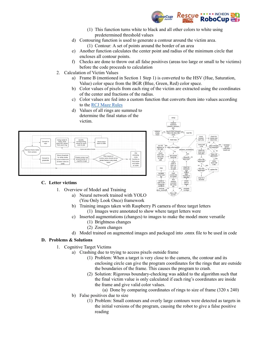
1. The main code pulls sensor values from the robot’s 6 Time-Of-Flight sensors in order to
determine where walls are for the tile that it is currently on. It averages the values from
sensors on the same side, and compares the value to a preset threshold of 12 cm and 17 cm for
walls in front and on the sides respectively. If two sides are giving conflicting values, the robot
will attempt to move back and forth in order to find a window where they agree.
C. Breadth-First Search (BFS)
1. The robot decides which tile to move to next using a breadth-first search algorithm. It also
uses this in order to find a path back to the starting tile for the end bonus. Breadth-first search
is an algorithm that uses nodes and checks each node at the present depth before moving onto
the next layer. This ensures the shortest possible path is found.
D. Ramps
1. Ramps are detected using the BNO055. The current pitch, or the Z orientation, is checked in
order to figure out whether or not the robot is on a ramp. From there, the robot adjusts its
speed accordingly until the pitch levels out again. The ramp logic can also be applied to stairs
since they also change the robot’s incline. The threshold for detecting a ramp is 15 degrees in
order to ensure a speed bump will not be detected as a ramp.
E. Colored Tiles
1. The APDS sensor is used to detect colored tiles. It returns red, green, blue, and clear values.
The values are compared to thresholds in order to determine whether a colored tile is being
detected. For example, for determining if a tile is silver, the clear value is compared since
silver reflects significantly more light than other colors like white and red. For red, the
red/blue ratio and the blue value is checked (blue is the blue/red ratio and the red value). This
helps rule out the other possible colors of white, silver, black, and blue. Black tiles are the last
checked as they have conditions which overlap with those of the red and blue tiles.
F. Victims
1. The robot must interpret values from the cameras and blink as well as distribute rescue kits
accordingly. The main code does this by sending a value through Serial1 to the Pi, which
triggers it to send the victim values it's detecting. The values are then interpreted and run
through separate functions of switch cases. These functions are responsible for blinking the
LED and dropping the rescue kits on the correct side. The cameras are checked every 15 cm
because the field of view for the cameras is not large enough for them to be checked every 30
cm.
G. Obstacles
1. The robot must be able to detect obstacles throughout the maze in a variety of positions. It
uses a combination of the two front TOFs and the L4CX wide range TOF in order to check for
obstacles. A system of if/else statements is used to sort the obstacles into distances (far or
close) and positions (center, left, or right). The walls are then marked in accordance with
where the obstacles are, and the robot might try to navigate around the obstacle if enough
space is possible. This is handled in a separate function of a switch case, which calls upon the
detection one and handles the position.
H. File system
1. If the robot hits a lack of progress, it must be able to recall the information it previously
gained from exploring the maze so that it does not waste time traversing those tiles again. In
order to do so, the robot uses the file system of the chip itself rather than the local memory
from running the code. It can then open the file and read back in all the information it has on
the maze.
I. Problems & Solutions
1. Robot was sensing the black tile, but continuing to try and traverse it rather than blocking it
off
a) The original code was marking the tile that the robot was trying to travel to as a hole
rather than the one that it was currently one
b) Fixed by switching variable names and running through code again to find similar
errors (blue tile had one where the target tile was being checked rather than the current
one)
2. Robot was moving backwards into walls because it couldn't check for them in the orientation
it was backing up in
a) The original code was having the robot move backward if the target tile could be
reached that way, regardless of if the tile had been previously checked for walls that
way
b) Fixed by adding an extra condition that the next tile that was being traversed to had to
be already visited in order to move backward since the walls for those are already
marked
3. Error was accumulating over time from both the IMU and encoders not being completely
perfect over time
a) Added corrections function that is called on throughout the code. This function checks
if there is a wall in front of it within 15 cm and uses that wall to straighten the robot
out and adjust its position on the tile. The adjustment is then saved as an error
correction that is applied to the return value from the function that checks for heading
values.
b) Also added an adjust function which is called when checking walls. This function
checks if the two sensors on the same side agree, and if they don't it tries moving both
forward and backward 7 cm in an attempt to get the sensors to agree on whether or not
they see a wall.
II. Victims
A. Tools
1. The algorithms for victim detection were created using the OpenCV library and the You Only
Look Once (YOLO) framework. Additionally, the Roboflow website was used to efficiently
create a large dataset for training a neural network model (further details in section C).
2. C libraries: cmath, string.h, lccv, opencv, dnn, highgui, ocl, iostream, fstream, thread, termios,
fcntl, signal, sstream
B. Cognitive target victims
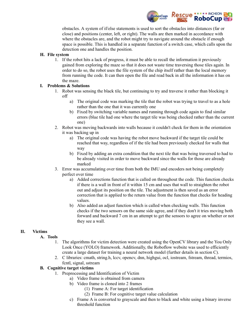
1. Preprocessing and Identification of Victim
a) Video frame is obtained from camera
b) Video frame is cloned into 2 frames
(1) Frame A: For target identification
(2) Frame B: For cognitive target value calculation
c) Frame A is converted to grayscale and then to black and white using a binary inverse
threshold function
(1) This function turns white to black and all other colors to white using
predetermined threshold values
d) Contouring function is used to generate a contour around the victim area.
(1) Contour: A set of points around the border of an area
e) Another function calculates the center point and radius of the minimum circle that
encloses all contour points.
f) Checks are done to throw out all false positives (areas too large or small to be victims)
before the code proceeds to calculation
2. Calculation of Victim Values
a) Frame B (mentioned in Section 1 Step 1) is converted to the HSV (Hue, Saturation,
Value) color space from the BGR (Blue, Green, Red) color space.
b) Color values of pixels from each ring of the victim are extracted using the coordinates
of the center and fractions of the radius.
c) Color values are fed into a custom function that converts them into values according
to the RCJ Maze Rules
d) Values of all rings are summed to
determine the final status of the
victim.
C. Letter victims
1. Overview of Model and Training
a) Neural network trained with YOLO
(You Only Look Once) framework
b) Training images taken with Raspberry Pi camera of three target letters
(1) Images were annotated to show where target letters were
c) Inserted augmentations (changes) to images to make the model more versatile
(1) Brightness changes
(2) Zoom changes
d) Model trained on augmented images and packaged into .onnx file to be used in code
D. Problems & Solutions
1. Cognitive Target Victims
a) Crashing due to trying to access pixels outside frame
(1) Problem: When a target is very close to the camera, the contour and its
enclosing circle can give the program coordinates for the rings that are outside
the boundaries of the frame. This causes the program to crash.
(2) Solution: Rigorous boundary-checking was added to the algorithm such that
the final victim value is only calculated if each ring’s coordinates are inside
the frame and give valid color values.
(a) Done by comparing coordinates of rings to size of frame (320 x 240)
b) False positives due to size
(1) Problem: Small contours and overly large contours were detected as targets in
the initial versions of the program, causing the robot to give a false positive
reading
(2) Solution: The initial structure of the program required it to iterate through all
contours and evaluate if each was a target. The program was modified to only
evaluate the value of the largest contour in the frame.
2. Letter Victims
a) False Positives due to Color
(1) Problem: The YOLO neural network would see colored tiles as ‘Omega’,
giving a false positive.
(2) Solution: Using the coordinates of the “letter” that the neural network gave as
output, the color value of the supposed “letter” was extracted. If the value was
not black or white (as it is supposed to be), it was thrown out as a false
positive.
c. Innovative solutions
● General maze
○ We use a 30x30 array to handle any starting position on the field
○ We use an obstacle classification system that utilizes three separate sensors to differentiate walls
from obstacles.
○ We use the built-in file system of the Pico in order to handle Lack of Progresses that we might
encounter without losing all previous progress.
○ We use an adjust function that moves back and forth in the case of the TOFs of one side not
agreeing on a distance value. In order to handle inevitable accumulated error over the course of the
maze, we use the walls themselves in order to align the robot during a run.
● Victim detection
○ YOLO architecture is used to recognize letter victims. Additional validation is also used to ensure
the neural network is not detecting a colored tile or other colored object as a victim.
○ Binary inverse thresholding and MinEnclosingCircle / HoughCircle functions are used to detect
cognitive target victims
3. Performance evaluation
● To rigorously verify the robot's performance against expected competition challenges , we implemented a
systematic testing procedure using a modular practice arena featuring standardized ramps, victims, decoy
victims, speed bumps, obstacles, and colored tiles. The robot achieved a high success rate in navigating these
scoring items. Most of our errors resulted from hardware issues, victim detection circumstances, and
navigation errors caused by obstacles and speed bumps. Hardware issues included brownouts and various
small wiring problems (such as a loose color sensor wire or overloaded battery). Victim detection issues
stemmed from a variety of circumstances, such as the victim being placed out of the camera’s field of view on
a tile or the light level causing the YOLO algorithm not to detect a letter victim. The introduction of the ring
light largely mitigated these. Finally, navigation errors caused by obstacles were prominent, as the robot was
knocked off course by speed bumps and obstacles. However, this was very rare and combated with the
introduction of the new robot chassis. While these critical factors did go wrong in testing, they were dealt with,
leaving the state of the robot as ready for the 2026 RCJ Maze competition.
4. Conclusion
This paper detailed the development of a fully autonomous robot designed for the RoboCupJunior Maze
competition. By utilizing a sensor array integrated with Breadth-First-Search, error correction, and victim
recognition algorithms, the robot successfully achieved a high reliability rate in navigating complex, uneven
terrain and identifying victims. While early iterations struggled with victim detection, protruding cameras,
brownouts, and size constraints, redesigning the chassis and victim detection algorithms reduced deployment
errors greatly. Ultimately, our rigorous testing proves the platform is robust, efficient, and highly capable of
meeting the stringent constraints of the 2026 RoboCup Junior Incheon competition environment.
10 pages, rendered as images so they load quickly. The text above is the document's own, extracted from the PDF.
Source code
The team's own source code, 14 KB. It is a download rather than part of this page, because a zip is something you open on your computer. It comes from GitHub, which some school networks block.