
Optimaze
Document register
- Poster1 pagePublished
- Presentation videoYouTubePublished
- Bill of materials119 KBPublished
- Team description paper14 pagesPublished
- Engineering journalNot shared
- Source codeNot shared
Sharing each document is the team's decision. “Not shared” means this team chose not to publish it, or did not submit one — not that it is missing from the archive.
In their words
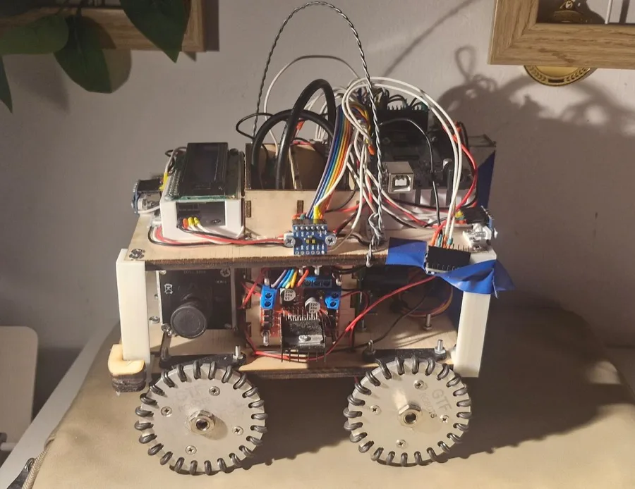
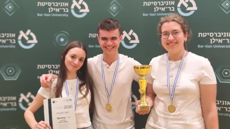
Our rescue robot has been designed to explore an unknown maze environment, find victims, and deliver the necessary rescue kits to them.
The hardware includes ToF sensors to detect the wall, an IMU sensor to track the orientation of the robot, a color sensor to recognize colored tiles, cameras to detect the victims, and a stepper motor to drop the rescue kits. For software and navigation, we used a BFS algorithm for both the mapping of the maze environment and the calculation of the optimal path to the victim.
What makes our robot unique is its error correction capabilities of the robot and accurate navigation in the maze. The use of the IMU sensor allows us to constantly correct any localization errors. With the error correction, the mapping, and the maze navigating technique, our robot will explore the whole maze and help the victims.
Poster
Read the text of this document — 744 words
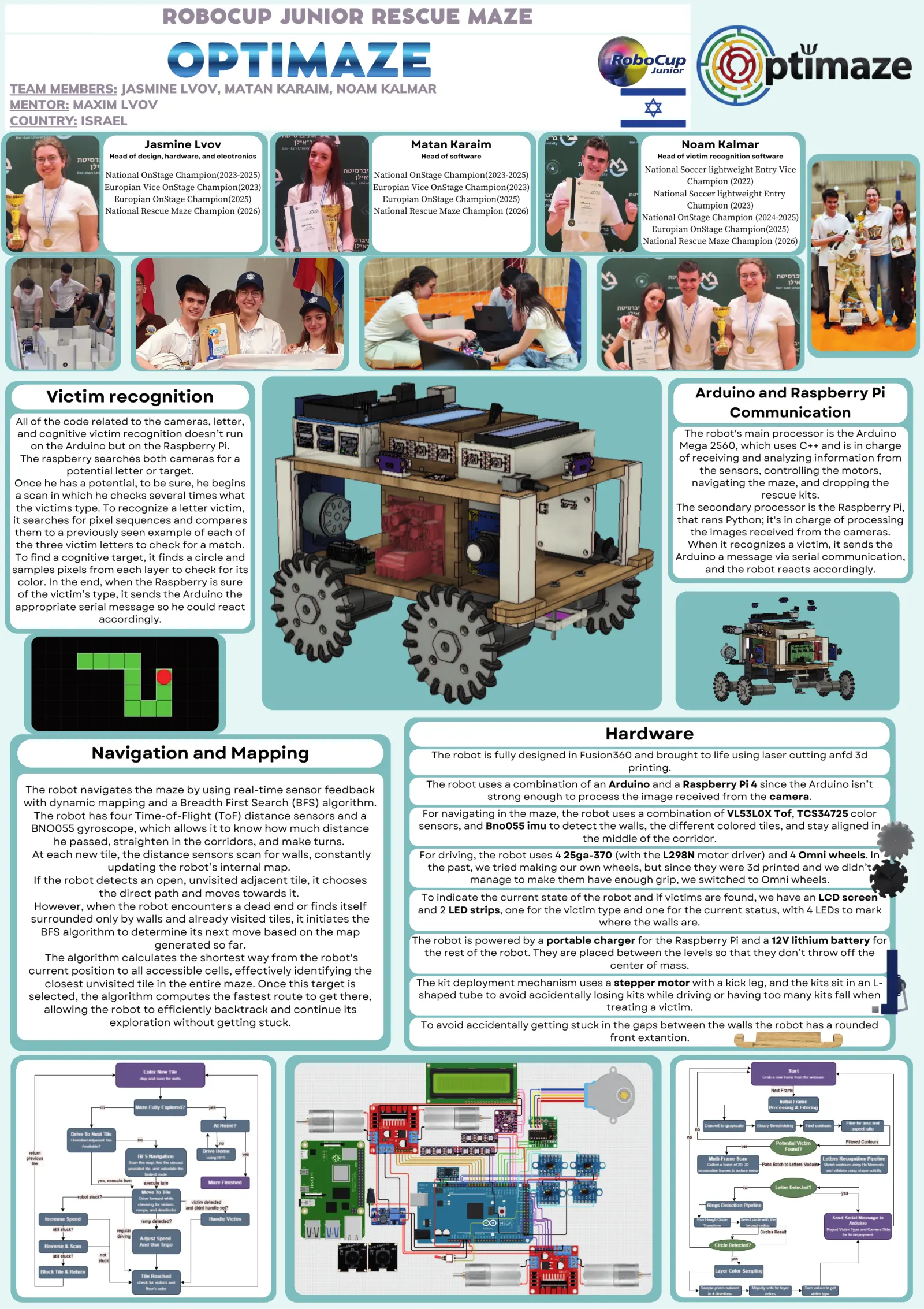
ROBOCUP JUNIOR RESCUE MAZE

                                   OPTIMAZE
TEAM MEMBERS: JASMINE LVOV, MATAN KARAIM, NOAM KALMAR
MENTOR: MAXIM LVOV
COUNTRY: ISRAEL
                             Jasmine Lvov                                      Matan Karaim                                            Noam Kalmar
                    Head of design, hardware, and electronics                     Head of software                               Head of victim recognition software

                                                                                                                              National Soccer lightweight Entry Vice
                   National OnStage Champion(2023-2025)                National OnStage Champion(2023-2025)
                                                                                                                                         Champion (2022)
                   Europian Vice OnStage Champion(2023)                Europian Vice OnStage Champion(2023)
                                                                                                                                National Soccer lightweight Entry
                     Europian OnStage Champion(2025)                     Europian OnStage Champion(2025)
                                                                                                                                         Champion (2023)
                   National Rescue Maze Champion (2026)                National Rescue Maze Champion (2026)
                                                                                                                              National OnStage Champion (2024-2025)
                                                                                                                                Europian OnStage Champion(2025)
                                                                                                                              National Rescue Maze Champion (2026)

       Victim recognition                                                                                                                  Arduino and Raspberry Pi
                                                                                                                                               Communication
 All of the code related to the cameras, letter,
  and cognitive victim recognition doesn’t run                                                                                          The robot's main processor is the Arduino
     on the Arduino but on the Raspberry Pi.                                                                                           Mega 2560, which uses C++ and is in charge
  The raspberry searches both cameras for a                                                                                            of receiving and analyzing information from
             potential letter or target.                                                                                                   the sensors, controlling the motors,
Once he has a potential, to be sure, he begins                                                                                            navigating the maze, and dropping the
 a scan in which he checks several times what                                                                                                          rescue kits.
 the victims type. To recognize a letter victim,                                                                                      The secondary processor is the Raspberry Pi,
it searches for pixel sequences and compares                                                                                          that rans Python; it's in charge of processing
 them to a previously seen example of each of                                                                                            the images received from the cameras.
 the three victim letters to check for a match.                                                                                          When it recognizes a victim, it sends the
 To find a cognitive target, it finds a circle and                                                                                    Arduino a message via serial communication,
samples pixels from each layer to check for its                                                                                             and the robot reacts accordingly.
  color. In the end, when the Raspberry is sure
  of the victim’s type, it sends the Arduino the
 appropriate serial message so he could react
                   accordingly.

                                                                                                                       Hardware
                Navigation and Mapping                                              The robot is fully designed in Fusion360 and brought to life using laser cutting anfd 3d
                                                                                                                           printing.
                                                                                   The robot uses a combination of an Arduino and a Raspberry Pi 4 since the Arduino isn’t
  The robot navigates the maze by using real-time sensor feedback
                                                                                              strong enough to process the image received from the camera.
  with dynamic mapping and a Breadth First Search (BFS) algorithm.
    The robot has four Time-of-Flight (ToF) distance sensors and a                For navigating in the maze, the robot uses a combination of VL53L0X Tof, TCS34725 color
   BNO055 gyroscope, which allows it to know how much distance                   sensors, and Bno055 imu to detect the walls, the different colored tiles, and stay aligned in
         he passed, straighten in the corridors, and make turns.                                                  the middle of the corridor.
    At each new tile, the distance sensors scan for walls, constantly            For driving, the robot uses 4 25ga-370 (with the L298N motor driver) and 4 Omni wheels. In
                    updating the robot’s internal map.                            the past, we tried making our own wheels, but since they were 3d printed and we didn’t
    If the robot detects an open, unvisited adjacent tile, it chooses                      manage to make them have enough grip, we switched to Omni wheels.
                  the direct path and moves towards it.                           To indicate the current state of the robot and if victims are found, we have an LCD screen
    However, when the robot encounters a dead end or finds itself                and 2 LED strips, one for the victim type and one for the current status, with 4 LEDs to mark
   surrounded only by walls and already visited tiles, it initiates the                                               where the walls are.
      BFS algorithm to determine its next move based on the map
                             generated so far.                                 The robot is powered by a portable charger for the Raspberry Pi and a 12V lithium battery for
                                                                                 the rest of the robot. They are placed between the levels so that they don’t throw off the
       The algorithm calculates the shortest way from the robot's
                                                                                                                      center of mass.
   current position to all accessible cells, effectively identifying the
       closest unvisited tile in the entire maze. Once this target is           The kit deployment mechanism uses a stepper motor with a kick leg, and the kits sit in an L-
   selected, the algorithm computes the fastest route to get there,             shaped tube to avoid accidentally losing kits while driving or having too many kits fall when
       allowing the robot to efficiently backtrack and continue its                                                  treating a victim.
                    exploration without getting stuck.                            To avoid accidentally getting stuck in the gaps between the walls the robot has a rounded
                                                                                                                        front extantion.
1 page, rendered as images so they load quickly. The text above is the document's own, extracted from the PDF.
Presentation video
Hosted on YouTube. The player loads only when you press play.
Bill of materials
Shown as the original PDF, because this one is smaller that way and its text stays selectable and searchable.
Team description paper
Show the remaining 11 pages
Read the text of this document — 5498 words
ROBOCUPJUNIOR RESCUE (MAZE) 2026
TEAM DESCRIPTION PAPER
Optimaze
Abstract
● Our rescue robot has been designed to explore an unknown maze environment, find victims, and
deliver the necessary rescue kits to them.
● The hardware includes ToF sensors to detect the wall, an IMU sensor to track the orientation of the
robot, a color sensor to recognize colored tiles, cameras to detect the victims, and a stepper motor to
drop the rescue kits. For software and navigation, we used a BFS algorithm for both the mapping of
the maze environment and the calculation of the optimal path to the victim.
● What makes our robot unique is its error correction capabilities of the robot and accurate navigation in
the maze. The use of the IMU sensor allows us to constantly correct any localization errors. With the
error correction, the mapping, and the maze navigating technique, our robot will explore the whole
maze and help the victims.
1. Introduction
a. Team
● Jasmine Lvov- Jasmine, an 11th-grade student, is majoring in physics and computer science.
● Role and contribution: Head of design, hardware, and electronics. Is in charge of designing and
assembling the different parts of the robot.
● Past Experience: She is a three-time national RoboCupJunior OnStage champion (2023–2025).
Internationally, she earned European Vice Champion honors in Croatia (2023) and became the
European Champion in Italy (2025), where she also won the SuperTeam prize.
● Matan Karaim- Matan, an 11th-grade student, is majoring in physics and computer science and is
earning a bachelor's degree in chemistry.
● Role and contribution: Head of software. Is responsible for creating the main Arduino firmware, the
robot's mapping algorithm, and navigation.
● Past Experience: She is a three-time national RoboCupJunior OnStage champion (2023–2025).
Internationally, she earned European Vice Champion honors in Croatia (2023) and became the
European Champion in Italy (2025), where she also won the SuperTeam prize.
● Noam Kalmar- Noam, a 10th-grade student, is majoring in physics and is earning a bachelor's degree
in computer science.
● Role and contribution: Is in charge of the Raspberry Pi and develops the logic for autonomous victim
detection and identification.
● Past Experience: He has competed in the Soccer league since 2022 and won the national Soccer
lightweight entry title in 2023 before transitioning to OnStage, becoming the national OnStage
champion for 2024–2025. Internationally, he won the TeamSpirit prize in Croatia (2023) and became
the European Champion in Italy (2025), where he also won the SuperTeam prize.
1
2. Project Planning
a. Overall Project Plan
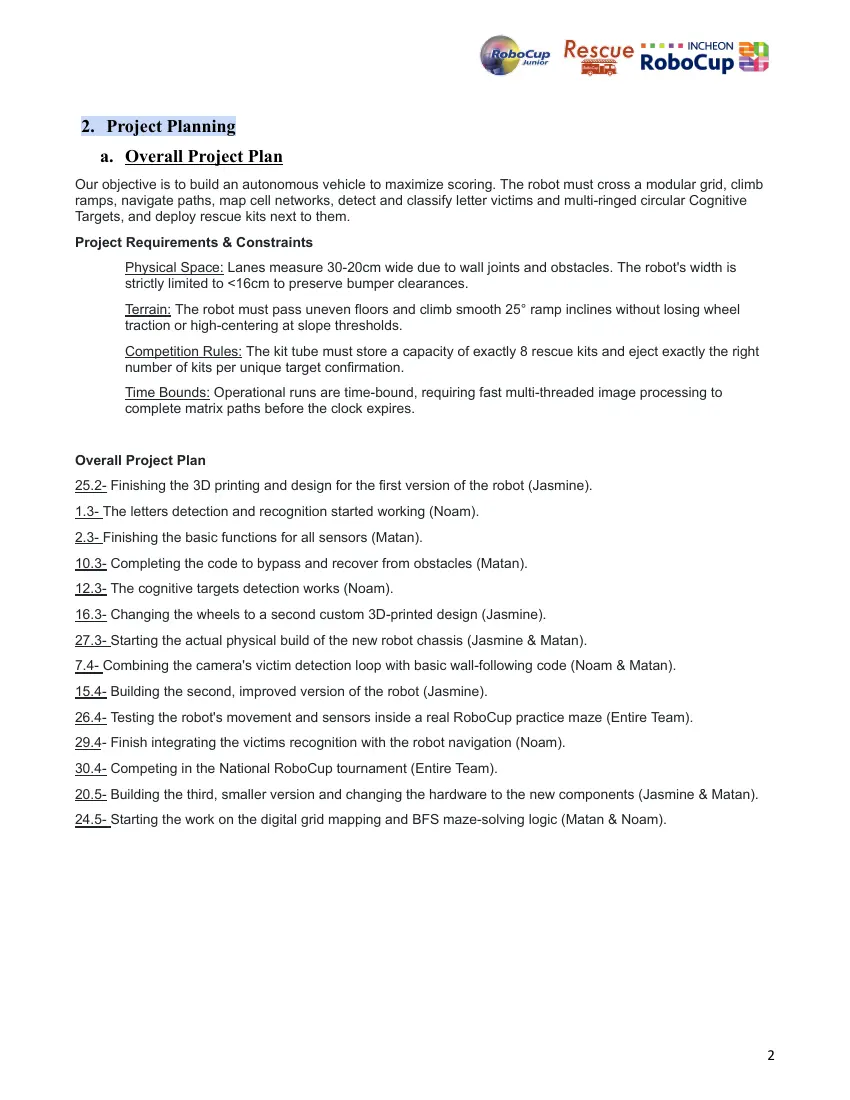
Our objective is to build an autonomous vehicle to maximize scoring. The robot must cross a modular grid, climb
ramps, navigate paths, map cell networks, detect and classify letter victims and multi-ringed circular Cognitive
Targets, and deploy rescue kits next to them.
Project Requirements & Constraints
Physical Space: Lanes measure 30-20cm wide due to wall joints and obstacles. The robot's width is
strictly limited to <16cm to preserve bumper clearances.
Terrain: The robot must pass uneven floors and climb smooth 25° ramp inclines without losing wheel
traction or high-centering at slope thresholds.
Competition Rules: The kit tube must store a capacity of exactly 8 rescue kits and eject exactly the right
number of kits per unique target confirmation.
Time Bounds: Operational runs are time-bound, requiring fast multi-threaded image processing to
complete matrix paths before the clock expires.
Overall Project Plan
25.2- Finishing the 3D printing and design for the first version of the robot (Jasmine).
1.3- The letters detection and recognition started working (Noam).
2.3- Finishing the basic functions for all sensors (Matan).
10.3- Completing the code to bypass and recover from obstacles (Matan).
12.3- The cognitive targets detection works (Noam).
16.3- Changing the wheels to a second custom 3D-printed design (Jasmine).
27.3- Starting the actual physical build of the new robot chassis (Jasmine & Matan).
7.4- Combining the camera's victim detection loop with basic wall-following code (Noam & Matan).
15.4- Building the second, improved version of the robot (Jasmine).
26.4- Testing the robot's movement and sensors inside a real RoboCup practice maze (Entire Team).
29.4- Finish integrating the victims recognition with the robot navigation (Noam).
30.4- Competing in the National RoboCup tournament (Entire Team).
20.5- Building the third, smaller version and changing the hardware to the new components (Jasmine & Matan).
24.5- Starting the work on the digital grid mapping and BFS maze-solving logic (Matan & Noam).
2
The Schedule and Plan
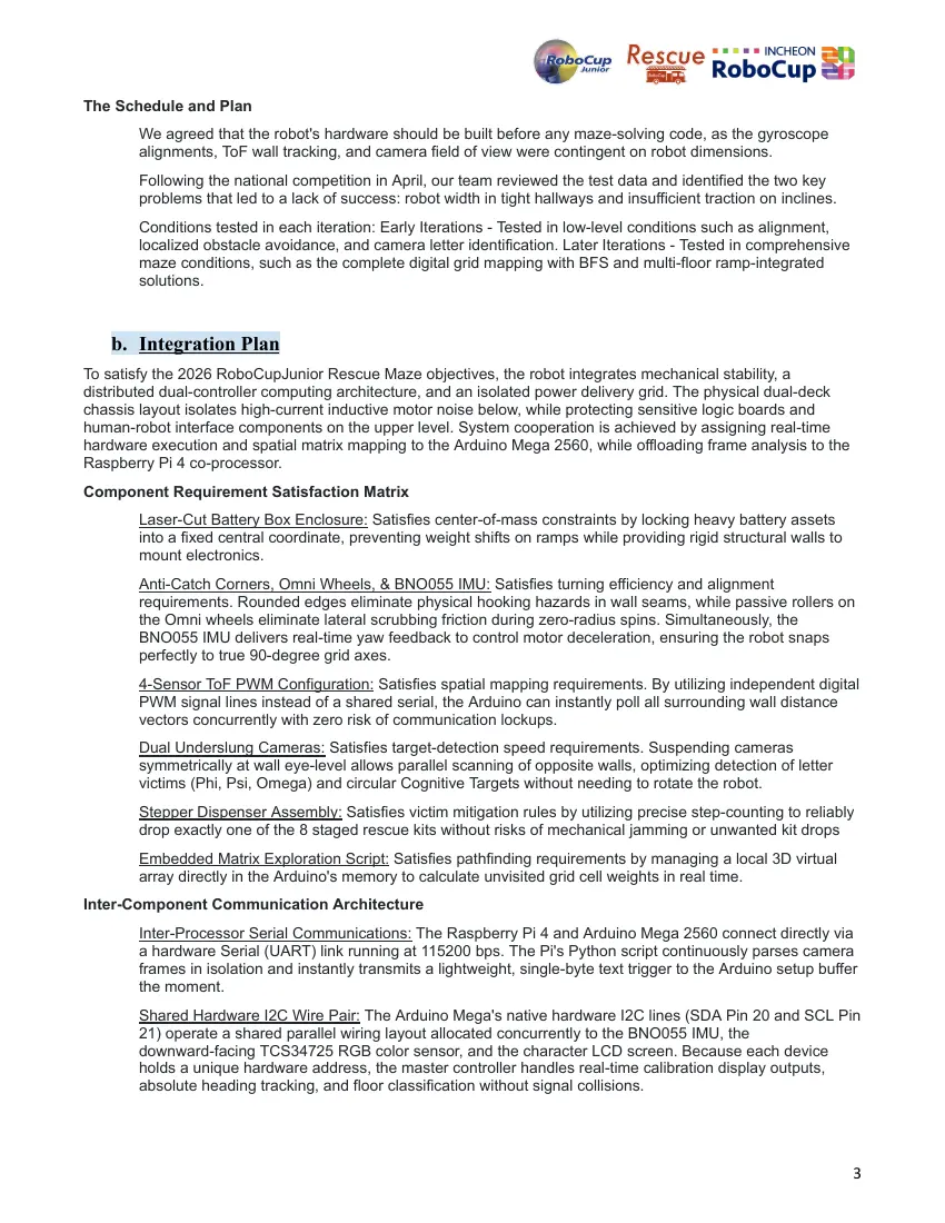
We agreed that the robot's hardware should be built before any maze-solving code, as the gyroscope
alignments, ToF wall tracking, and camera field of view were contingent on robot dimensions.
Following the national competition in April, our team reviewed the test data and identified the two key
problems that led to a lack of success: robot width in tight hallways and insufficient traction on inclines.
Conditions tested in each iteration: Early Iterations - Tested in low-level conditions such as alignment,
localized obstacle avoidance, and camera letter identification. Later Iterations - Tested in comprehensive
maze conditions, such as the complete digital grid mapping with BFS and multi-floor ramp-integrated
solutions.
b. Integration Plan
To satisfy the 2026 RoboCupJunior Rescue Maze objectives, the robot integrates mechanical stability, a
distributed dual-controller computing architecture, and an isolated power delivery grid. The physical dual-deck
chassis layout isolates high-current inductive motor noise below, while protecting sensitive logic boards and
human-robot interface components on the upper level. System cooperation is achieved by assigning real-time
hardware execution and spatial matrix mapping to the Arduino Mega 2560, while offloading frame analysis to the
Raspberry Pi 4 co-processor.
Component Requirement Satisfaction Matrix
Laser-Cut Battery Box Enclosure: Satisfies center-of-mass constraints by locking heavy battery assets
into a fixed central coordinate, preventing weight shifts on ramps while providing rigid structural walls to
mount electronics.
Anti-Catch Corners, Omni Wheels, & BNO055 IMU: Satisfies turning efficiency and alignment
requirements. Rounded edges eliminate physical hooking hazards in wall seams, while passive rollers on
the Omni wheels eliminate lateral scrubbing friction during zero-radius spins. Simultaneously, the
BNO055 IMU delivers real-time yaw feedback to control motor deceleration, ensuring the robot snaps
perfectly to true 90-degree grid axes.
4-Sensor ToF PWM Configuration: Satisfies spatial mapping requirements. By utilizing independent digital
PWM signal lines instead of a shared serial, the Arduino can instantly poll all surrounding wall distance
vectors concurrently with zero risk of communication lockups.
Dual Underslung Cameras: Satisfies target-detection speed requirements. Suspending cameras
symmetrically at wall eye-level allows parallel scanning of opposite walls, optimizing detection of letter
victims (Phi, Psi, Omega) and circular Cognitive Targets without needing to rotate the robot.
Stepper Dispenser Assembly: Satisfies victim mitigation rules by utilizing precise step-counting to reliably
drop exactly one of the 8 staged rescue kits without risks of mechanical jamming or unwanted kit drops
Embedded Matrix Exploration Script: Satisfies pathfinding requirements by managing a local 3D virtual
array directly in the Arduino's memory to calculate unvisited grid cell weights in real time.
Inter-Component Communication Architecture
Inter-Processor Serial Communications: The Raspberry Pi 4 and Arduino Mega 2560 connect directly via
a hardware Serial (UART) link running at 115200 bps. The Pi's Python script continuously parses camera
frames in isolation and instantly transmits a lightweight, single-byte text trigger to the Arduino setup buffer
the moment.
Shared Hardware I2C Wire Pair: The Arduino Mega's native hardware I2C lines (SDA Pin 20 and SCL Pin
21) operate a shared parallel wiring layout allocated concurrently to the BNO055 IMU, the
downward-facing TCS34725 RGB color sensor, and the character LCD screen. Because each device
holds a unique hardware address, the master controller handles real-time calibration display outputs,
absolute heading tracking, and floor classification without signal collisions.
3
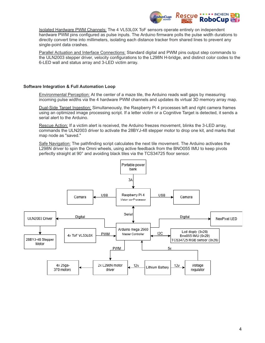
Isolated Hardware PWM Channels: The 4 VL53L0X ToF sensors operate entirely on independent
hardware PWM pins configured as pulse inputs. The Arduino firmware polls the pulse width durations to
directly convert time into millimeters, isolating each distance tracker from shared lines to prevent any
single-point data crashes.
Parallel Actuation and Interface Connections: Standard digital and PWM pins output step commands to
the ULN2003 stepper driver, velocity configurations to the L298N H-bridge, and distinct color codes to the
6-LED wall and status array and 3-LED victim array.
Software Integration & Full Automation Loop
Environmental Perception: At the center of a maze tile, the Arduino reads wall gaps by measuring
incoming pulse widths via the 4 hardware PWM channels and updates its virtual 3D memory array map.
Dual-Side Target Ingestion: Simultaneously, the Raspberry Pi 4 processes left and right camera frames
using an optimized image processing script. If a letter victim or a Cognitive Target is detected, it sends a
serial alert to the Arduino.
Rescue Action: If a victim alert is received, the Arduino freezes movement, blinks the 3-LED array,
commands the ULN2003 driver to activate the 28BYJ-48 stepper motor to drop one kit, and marks that
map node as "saved."
Safe Navigation: The pathfinding script calculates the next tile movement. The Arduino activates the
L298N driver to spin the Omni wheels, using active feedback from the BNO055 IMU to keep pivots
perfectly straight at 90° and avoiding black tiles via the TCS34725 floor sensor.
4
3. Hardware
Overview
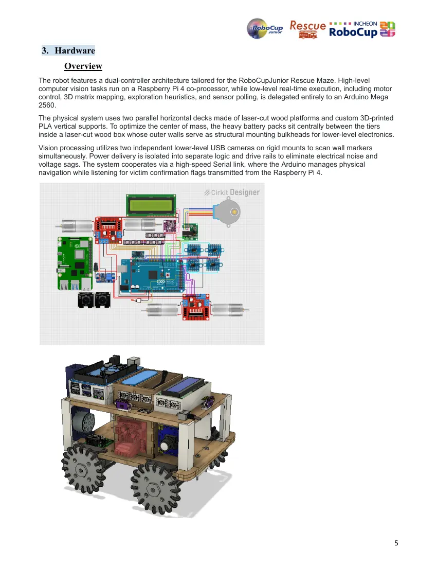
The robot features a dual-controller architecture tailored for the RoboCupJunior Rescue Maze. High-level
computer vision tasks run on a Raspberry Pi 4 co-processor, while low-level real-time execution, including motor
control, 3D matrix mapping, exploration heuristics, and sensor polling, is delegated entirely to an Arduino Mega
2560.
The physical system uses two parallel horizontal decks made of laser-cut wood platforms and custom 3D-printed
PLA vertical supports. To optimize the center of mass, the heavy battery packs sit centrally between the tiers
inside a laser-cut wood box whose outer walls serve as structural mounting bulkheads for lower-level electronics.
Vision processing utilizes two independent lower-level USB cameras on rigid mounts to scan wall markers
simultaneously. Power delivery is isolated into separate logic and drive rails to eliminate electrical noise and
voltage sags. The system cooperates via a high-speed Serial link, where the Arduino manages physical
navigation while listening for victim confirmation flags transmitted from the Raspberry Pi 4.
5
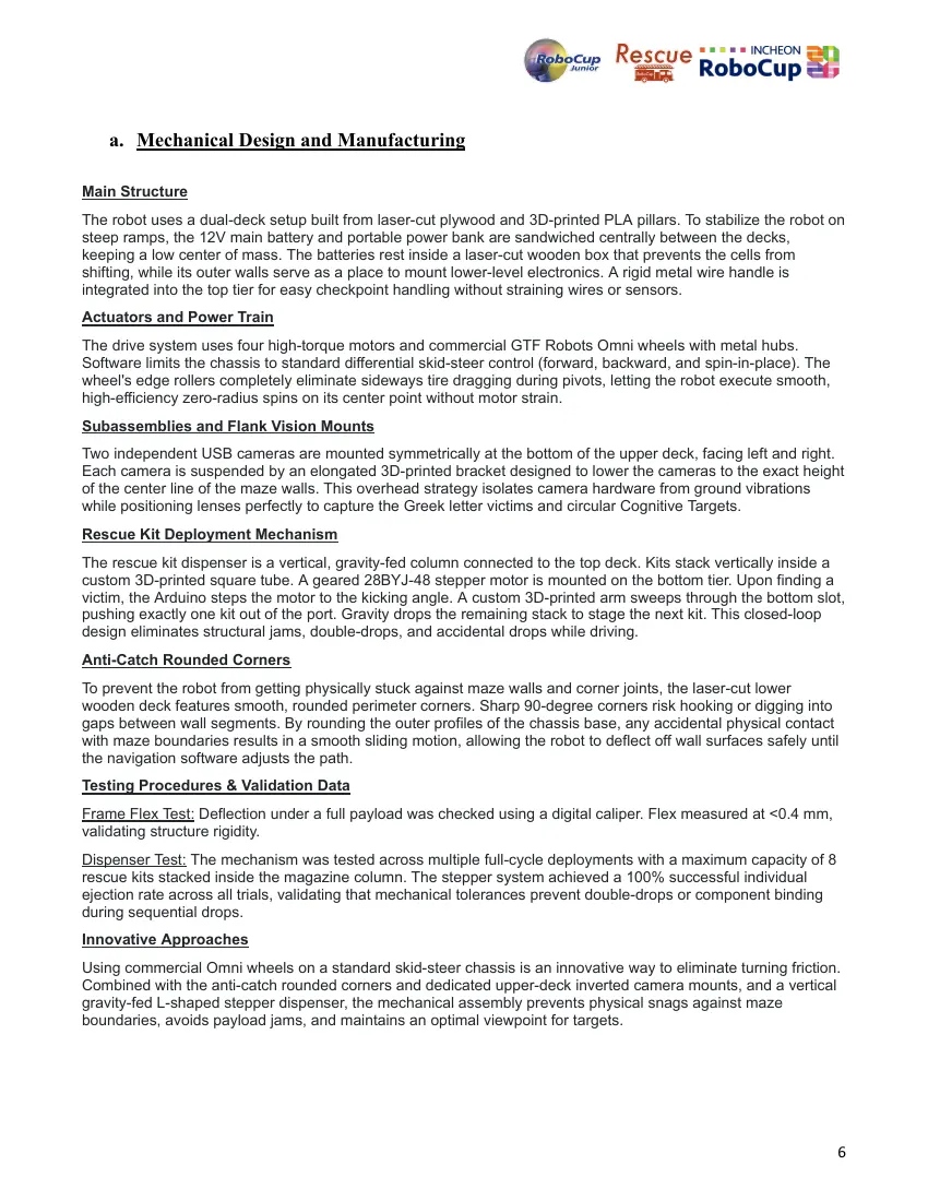
a. Mechanical Design and Manufacturing
Main Structure
The robot uses a dual-deck setup built from laser-cut plywood and 3D-printed PLA pillars. To stabilize the robot on
steep ramps, the 12V main battery and portable power bank are sandwiched centrally between the decks,
keeping a low center of mass. The batteries rest inside a laser-cut wooden box that prevents the cells from
shifting, while its outer walls serve as a place to mount lower-level electronics. A rigid metal wire handle is
integrated into the top tier for easy checkpoint handling without straining wires or sensors.
Actuators and Power Train
The drive system uses four high-torque motors and commercial GTF Robots Omni wheels with metal hubs.
Software limits the chassis to standard differential skid-steer control (forward, backward, and spin-in-place). The
wheel's edge rollers completely eliminate sideways tire dragging during pivots, letting the robot execute smooth,
high-efficiency zero-radius spins on its center point without motor strain.
Subassemblies and Flank Vision Mounts
Two independent USB cameras are mounted symmetrically at the bottom of the upper deck, facing left and right.
Each camera is suspended by an elongated 3D-printed bracket designed to lower the cameras to the exact height
of the center line of the maze walls. This overhead strategy isolates camera hardware from ground vibrations
while positioning lenses perfectly to capture the Greek letter victims and circular Cognitive Targets.
Rescue Kit Deployment Mechanism
The rescue kit dispenser is a vertical, gravity-fed column connected to the top deck. Kits stack vertically inside a
custom 3D-printed square tube. A geared 28BYJ-48 stepper motor is mounted on the bottom tier. Upon finding a
victim, the Arduino steps the motor to the kicking angle. A custom 3D-printed arm sweeps through the bottom slot,
pushing exactly one kit out of the port. Gravity drops the remaining stack to stage the next kit. This closed-loop
design eliminates structural jams, double-drops, and accidental drops while driving.
Anti-Catch Rounded Corners
To prevent the robot from getting physically stuck against maze walls and corner joints, the laser-cut lower
wooden deck features smooth, rounded perimeter corners. Sharp 90-degree corners risk hooking or digging into
gaps between wall segments. By rounding the outer profiles of the chassis base, any accidental physical contact
with maze boundaries results in a smooth sliding motion, allowing the robot to deflect off wall surfaces safely until
the navigation software adjusts the path.
Testing Procedures & Validation Data
Frame Flex Test: Deflection under a full payload was checked using a digital caliper. Flex measured at <0.4 mm,
validating structure rigidity.
Dispenser Test: The mechanism was tested across multiple full-cycle deployments with a maximum capacity of 8
rescue kits stacked inside the magazine column. The stepper system achieved a 100% successful individual
ejection rate across all trials, validating that mechanical tolerances prevent double-drops or component binding
during sequential drops.
Innovative Approaches
Using commercial Omni wheels on a standard skid-steer chassis is an innovative way to eliminate turning friction.
Combined with the anti-catch rounded corners and dedicated upper-deck inverted camera mounts, and a vertical
gravity-fed L-shaped stepper dispenser, the mechanical assembly prevents physical snags against maze
boundaries, avoids payload jams, and maintains an optimal viewpoint for targets.
6
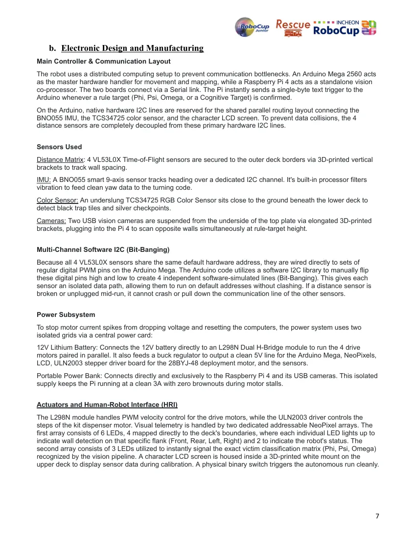
b. Electronic Design and Manufacturing
Main Controller & Communication Layout
The robot uses a distributed computing setup to prevent communication bottlenecks. An Arduino Mega 2560 acts
as the master hardware handler for movement and mapping, while a Raspberry Pi 4 acts as a standalone vision
co-processor. The two boards connect via a Serial link. The Pi instantly sends a single-byte text trigger to the
Arduino whenever a rule target (Phi, Psi, Omega, or a Cognitive Target) is confirmed.
On the Arduino, native hardware I2C lines are reserved for the shared parallel routing layout connecting the
BNO055 IMU, the TCS34725 color sensor, and the character LCD screen. To prevent data collisions, the 4
distance sensors are completely decoupled from these primary hardware I2C lines.
Sensors Used
Distance Matrix: 4 VL53L0X Time-of-Flight sensors are secured to the outer deck borders via 3D-printed vertical
brackets to track wall spacing.
IMU: A BNO055 smart 9-axis sensor tracks heading over a dedicated I2C channel. It's built-in processor filters
vibration to feed clean yaw data to the turning code.
Color Sensor: An underslung TCS34725 RGB Color Sensor sits close to the ground beneath the lower deck to
detect black trap tiles and silver checkpoints.
Cameras: Two USB vision cameras are suspended from the underside of the top plate via elongated 3D-printed
brackets, plugging into the Pi 4 to scan opposite walls simultaneously at rule-target height.
Multi-Channel Software I2C (Bit-Banging)
Because all 4 VL53L0X sensors share the same default hardware address, they are wired directly to sets of
regular digital PWM pins on the Arduino Mega. The Arduino code utilizes a software I2C library to manually flip
these digital pins high and low to create 4 independent software-simulated lines (Bit-Banging). This gives each
sensor an isolated data path, allowing them to run on default addresses without clashing. If a distance sensor is
broken or unplugged mid-run, it cannot crash or pull down the communication line of the other sensors.
Power Subsystem
To stop motor current spikes from dropping voltage and resetting the computers, the power system uses two
isolated grids via a central power card:
12V Lithium Battery: Connects the 12V battery directly to an L298N Dual H-Bridge module to run the 4 drive
motors paired in parallel. It also feeds a buck regulator to output a clean 5V line for the Arduino Mega, NeoPixels,
LCD, ULN2003 stepper driver board for the 28BYJ-48 deployment motor, and the sensors.
Portable Power Bank: Connects directly and exclusively to the Raspberry Pi 4 and its USB cameras. This isolated
supply keeps the Pi running at a clean 3A with zero brownouts during motor stalls.
Actuators and Human-Robot Interface (HRI)
The L298N module handles PWM velocity control for the drive motors, while the ULN2003 driver controls the
steps of the kit dispenser motor. Visual telemetry is handled by two dedicated addressable NeoPixel arrays. The
first array consists of 6 LEDs, 4 mapped directly to the deck's boundaries, where each individual LED lights up to
indicate wall detection on that specific flank (Front, Rear, Left, Right) and 2 to indicate the robot's status. The
second array consists of 3 LEDs utilized to instantly signal the exact victim classification matrix (Phi, Psi, Omega)
recognized by the vision pipeline. A character LCD screen is housed inside a 3D-printed white mount on the
upper deck to display sensor data during calibration. A physical binary switch triggers the autonomous run cleanly.
7
Testing Procedures & Validation Data
Voltage Sag Test: The rails were monitored under motor stall conditions. The motor battery experienced dips, but
the isolated power bank kept the Pi 4 perfectly stable at 3A with zero resets.
Innovative Approaches
Using independent hardware PWM pins to create individual software-simulated I2C paths (Bit-Banging) for the 4
distance sensors. It eliminates the need for an external multiplexer chip, protects the robot from single-point
sensor failures, and leaves the Arduino's main lines free to parse the IMU, LCD, and color sensor without data
delays.
8
4. Software
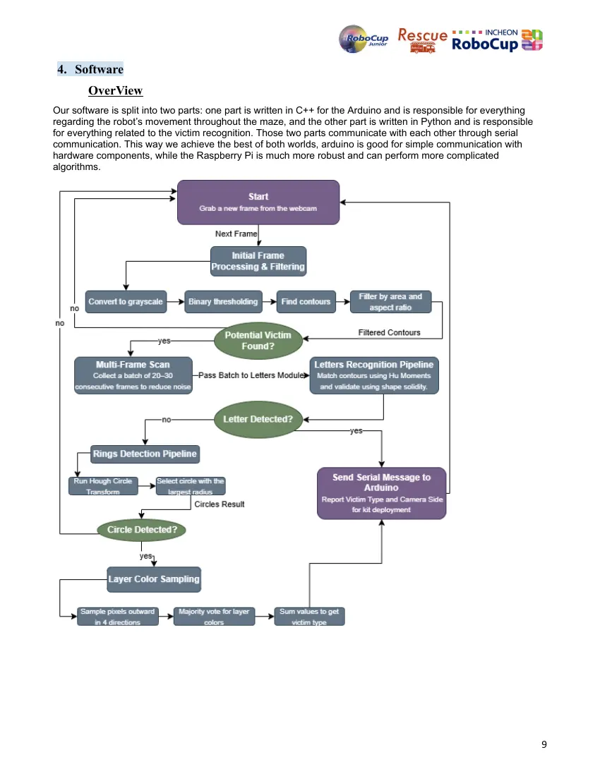
OverView
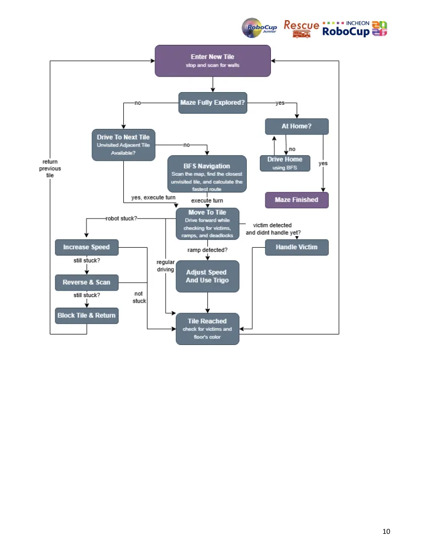
Our software is split into two parts: one part is written in C++ for the Arduino and is responsible for everything
regarding the robot’s movement throughout the maze, and the other part is written in Python and is responsible
for everything related to the victim recognition. Those two parts communicate with each other through serial
communication. This way we achieve the best of both worlds, arduino is good for simple communication with
hardware components, while the Raspberry Pi is much more robust and can perform more complicated
algorithms.
9
10
a. General software architecture
Python Code
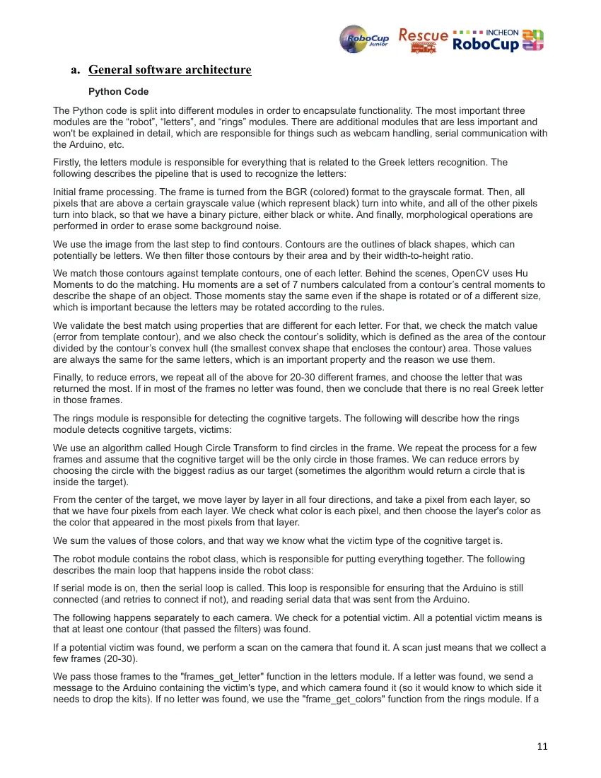
The Python code is split into different modules in order to encapsulate functionality. The most important three
modules are the “robot”, “letters”, and “rings” modules. There are additional modules that are less important and
won't be explained in detail, which are responsible for things such as webcam handling, serial communication with
the Arduino, etc.
Firstly, the letters module is responsible for everything that is related to the Greek letters recognition. The
following describes the pipeline that is used to recognize the letters:
Initial frame processing. The frame is turned from the BGR (colored) format to the grayscale format. Then, all
pixels that are above a certain grayscale value (which represent black) turn into white, and all of the other pixels
turn into black, so that we have a binary picture, either black or white. And finally, morphological operations are
performed in order to erase some background noise.
We use the image from the last step to find contours. Contours are the outlines of black shapes, which can
potentially be letters. We then filter those contours by their area and by their width-to-height ratio.
We match those contours against template contours, one of each letter. Behind the scenes, OpenCV uses Hu
Moments to do the matching. Hu moments are a set of 7 numbers calculated from a contour’s central moments to
describe the shape of an object. Those moments stay the same even if the shape is rotated or of a different size,
which is important because the letters may be rotated according to the rules.
We validate the best match using properties that are different for each letter. For that, we check the match value
(error from template contour), and we also check the contour’s solidity, which is defined as the area of the contour
divided by the contour’s convex hull (the smallest convex shape that encloses the contour) area. Those values
are always the same for the same letters, which is an important property and the reason we use them.
Finally, to reduce errors, we repeat all of the above for 20-30 different frames, and choose the letter that was
returned the most. If in most of the frames no letter was found, then we conclude that there is no real Greek letter
in those frames.
The rings module is responsible for detecting the cognitive targets. The following will describe how the rings
module detects cognitive targets, victims:
We use an algorithm called Hough Circle Transform to find circles in the frame. We repeat the process for a few
frames and assume that the cognitive target will be the only circle in those frames. We can reduce errors by
choosing the circle with the biggest radius as our target (sometimes the algorithm would return a circle that is
inside the target).
From the center of the target, we move layer by layer in all four directions, and take a pixel from each layer, so
that we have four pixels from each layer. We check what color is each pixel, and then choose the layer's color as
the color that appeared in the most pixels from that layer.
We sum the values of those colors, and that way we know what the victim type of the cognitive target is.
The robot module contains the robot class, which is responsible for putting everything together. The following
describes the main loop that happens inside the robot class:
If serial mode is on, then the serial loop is called. This loop is responsible for ensuring that the Arduino is still
connected (and retries to connect if not), and reading serial data that was sent from the Arduino.
The following happens separately to each camera. We check for a potential victim. All a potential victim means is
that at least one contour (that passed the filters) was found.
If a potential victim was found, we perform a scan on the camera that found it. A scan just means that we collect a
few frames (20-30).
We pass those frames to the "frames_get_letter" function in the letters module. If a letter was found, we send a
message to the Arduino containing the victim's type, and which camera found it (so it would know to which side it
needs to drop the kits). If no letter was found, we use the "frame_get_colors" function from the rings module. If a
11
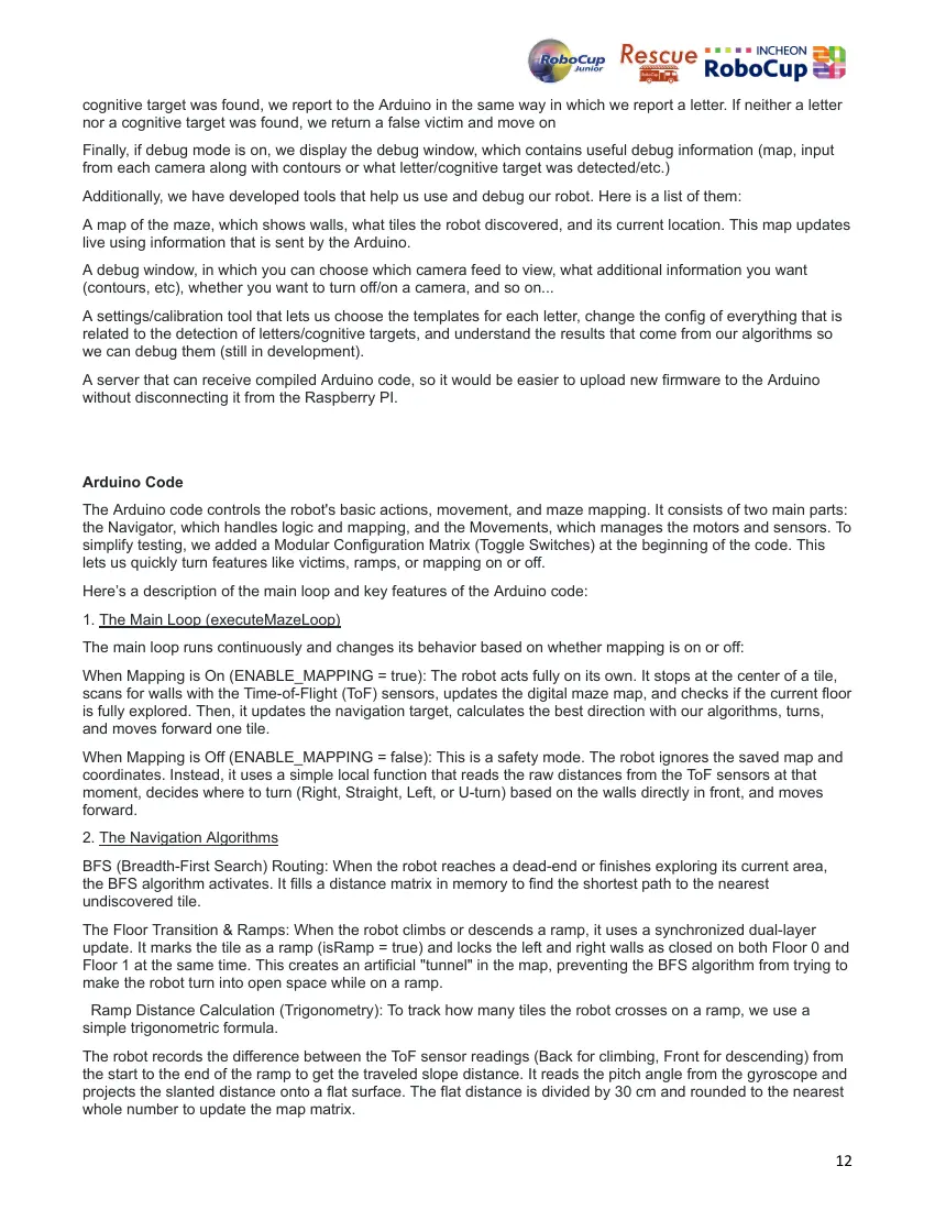
cognitive target was found, we report to the Arduino in the same way in which we report a letter. If neither a letter
nor a cognitive target was found, we return a false victim and move on
Finally, if debug mode is on, we display the debug window, which contains useful debug information (map, input
from each camera along with contours or what letter/cognitive target was detected/etc.)
Additionally, we have developed tools that help us use and debug our robot. Here is a list of them:
A map of the maze, which shows walls, what tiles the robot discovered, and its current location. This map updates
live using information that is sent by the Arduino.
A debug window, in which you can choose which camera feed to view, what additional information you want
(contours, etc), whether you want to turn off/on a camera, and so on...
A settings/calibration tool that lets us choose the templates for each letter, change the config of everything that is
related to the detection of letters/cognitive targets, and understand the results that come from our algorithms so
we can debug them (still in development).
A server that can receive compiled Arduino code, so it would be easier to upload new firmware to the Arduino
without disconnecting it from the Raspberry PI.
Arduino Code
The Arduino code controls the robot's basic actions, movement, and maze mapping. It consists of two main parts:
the Navigator, which handles logic and mapping, and the Movements, which manages the motors and sensors. To
simplify testing, we added a Modular Configuration Matrix (Toggle Switches) at the beginning of the code. This
lets us quickly turn features like victims, ramps, or mapping on or off.
Here’s a description of the main loop and key features of the Arduino code:
1. The Main Loop (executeMazeLoop)
The main loop runs continuously and changes its behavior based on whether mapping is on or off:
When Mapping is On (ENABLE_MAPPING = true): The robot acts fully on its own. It stops at the center of a tile,
scans for walls with the Time-of-Flight (ToF) sensors, updates the digital maze map, and checks if the current floor
is fully explored. Then, it updates the navigation target, calculates the best direction with our algorithms, turns,
and moves forward one tile.
When Mapping is Off (ENABLE_MAPPING = false): This is a safety mode. The robot ignores the saved map and
coordinates. Instead, it uses a simple local function that reads the raw distances from the ToF sensors at that
moment, decides where to turn (Right, Straight, Left, or U-turn) based on the walls directly in front, and moves
forward.
2. The Navigation Algorithms
BFS (Breadth-First Search) Routing: When the robot reaches a dead-end or finishes exploring its current area,
the BFS algorithm activates. It fills a distance matrix in memory to find the shortest path to the nearest
undiscovered tile.
The Floor Transition & Ramps: When the robot climbs or descends a ramp, it uses a synchronized dual-layer
update. It marks the tile as a ramp (isRamp = true) and locks the left and right walls as closed on both Floor 0 and
Floor 1 at the same time. This creates an artificial "tunnel" in the map, preventing the BFS algorithm from trying to
make the robot turn into open space while on a ramp.
Ramp Distance Calculation (Trigonometry): To track how many tiles the robot crosses on a ramp, we use a
simple trigonometric formula.
The robot records the difference between the ToF sensor readings (Back for climbing, Front for descending) from
the start to the end of the ramp to get the traveled slope distance. It reads the pitch angle from the gyroscope and
projects the slanted distance onto a flat surface. The flat distance is divided by 30 cm and rounded to the nearest
whole number to update the map matrix.
12
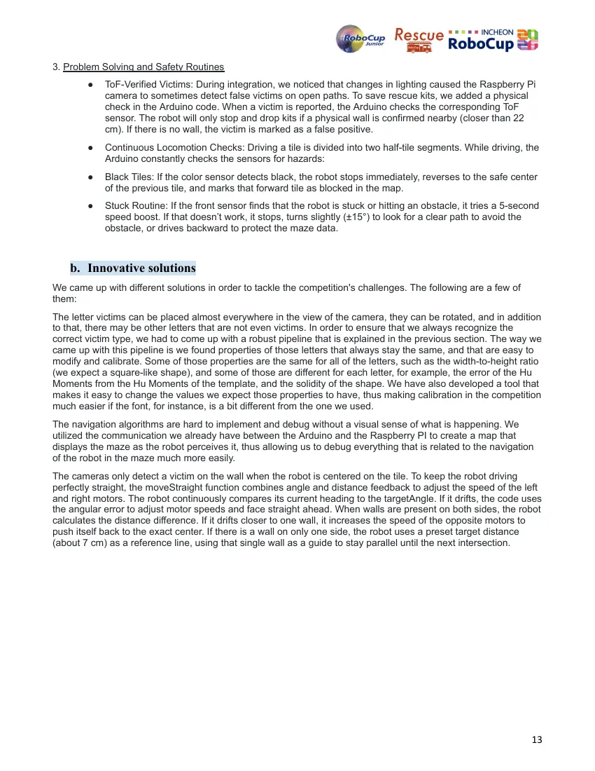
3. Problem Solving and Safety Routines
● ToF-Verified Victims: During integration, we noticed that changes in lighting caused the Raspberry Pi
camera to sometimes detect false victims on open paths. To save rescue kits, we added a physical
check in the Arduino code. When a victim is reported, the Arduino checks the corresponding ToF
sensor. The robot will only stop and drop kits if a physical wall is confirmed nearby (closer than 22
cm). If there is no wall, the victim is marked as a false positive.
● Continuous Locomotion Checks: Driving a tile is divided into two half-tile segments. While driving, the
Arduino constantly checks the sensors for hazards:
● Black Tiles: If the color sensor detects black, the robot stops immediately, reverses to the safe center
of the previous tile, and marks that forward tile as blocked in the map.
● Stuck Routine: If the front sensor finds that the robot is stuck or hitting an obstacle, it tries a 5-second
speed boost. If that doesn’t work, it stops, turns slightly (±15°) to look for a clear path to avoid the
obstacle, or drives backward to protect the maze data.
b. Innovative solutions
We came up with different solutions in order to tackle the competition's challenges. The following are a few of
them:
The letter victims can be placed almost everywhere in the view of the camera, they can be rotated, and in addition
to that, there may be other letters that are not even victims. In order to ensure that we always recognize the
correct victim type, we had to come up with a robust pipeline that is explained in the previous section. The way we
came up with this pipeline is we found properties of those letters that always stay the same, and that are easy to
modify and calibrate. Some of those properties are the same for all of the letters, such as the width-to-height ratio
(we expect a square-like shape), and some of those are different for each letter, for example, the error of the Hu
Moments from the Hu Moments of the template, and the solidity of the shape. We have also developed a tool that
makes it easy to change the values we expect those properties to have, thus making calibration in the competition
much easier if the font, for instance, is a bit different from the one we used.
The navigation algorithms are hard to implement and debug without a visual sense of what is happening. We
utilized the communication we already have between the Arduino and the Raspberry PI to create a map that
displays the maze as the robot perceives it, thus allowing us to debug everything that is related to the navigation
of the robot in the maze much more easily.
The cameras only detect a victim on the wall when the robot is centered on the tile. To keep the robot driving
perfectly straight, the moveStraight function combines angle and distance feedback to adjust the speed of the left
and right motors. The robot continuously compares its current heading to the targetAngle. If it drifts, the code uses
the angular error to adjust motor speeds and face straight ahead. When walls are present on both sides, the robot
calculates the distance difference. If it drifts closer to one wall, it increases the speed of the opposite motors to
push itself back to the exact center. If there is a wall on only one side, the robot uses a preset target distance
(about 7 cm) as a reference line, using that single wall as a guide to stay parallel until the next intersection.
13
5. Performance evaluation
We have continuously tested our robot in a structured way, trying to solve the challenges presented in the
RoboCup Junior Rescue Maze. In this section, we analyzed failures in our tests and tried to improve our software
and hardware:
Our performance against competition challenges:
Distance Calculation of Ramp: As we don't have wheel encoders for our robot, we cannot count distance by wheel
rotation. The distance on the map is therefore measured with a formula based on the gyroscope and the ToF
sensor, which detects how far the robot moves horizontally, instead of slanted along the slope.
Camera field of view and stopping logic: Our cameras originally had a really small field of view, so that our robot
had to turn almost 90 degrees in place just to "see" a wall. During our tests, even with fisheye lenses, it seemed
our robot still missed the victims at the far end of the wall. We now stop twice in each tile, thus halving the tile
size. The robot always turns on the spot, but it moves twice, which saves a lot of time. This also completely
removed the problem of missing victims on our tests.
Obstacle and Stuck Recovery: It happened that the robot got high-centered or simply got blocked by debris in the
arena. So the robot had to reverse and mark the tile in front of it as a blocked tile, which means it couldn't
continue mapping the rest of the room. In order to get rid of that, the robot now has a specific handleStuckRoutine
to clear the obstacle. First, we increased the speed of our robot for 5 seconds in order to try to push it past small
obstacles, then we programmed it to turn and to scan locally.
6. Conclusion
We started building our robot, "Vision", in March this year, only a month and a half before our national
competition. We all have experience in robotics and RoboCup Junior, but we are new to this category, so we had
to figure out everything from zero. We faced many challenges, both hardware and software related, that rose from
the complexity of what's required from our robot by the rules of the competition. What's common for all of those
challenges is that we solved them by quickly iterating through different versions while using a trial and error
approach. Because of our late start, we had very few resources (both time and material), therefore we had to be
very efficient and productive. We organized all of the work that needed to be done into different tasks, and each
team member was assigned tasks that would fit them the best because of their knowledge and experience. After
many iterations, we came up with the final version of "Vision", our robot. Vision consists of an Arduino Mega
board, which controls all of the hardware, both output (motors, kit dropper), and input (TOF sensors, color sensor,
IMU, etc.), except for the cameras. Additionally, the robot has a Raspberry PI board, which is responsible for
processing the live feeds that come from the robot's cameras and detecting victims. Those two main components,
the Arduino and the Raspberry PI, communicate with each other through serial communication, thus allowing us
to achieve the best of both worlds.
References
● See BOM
14
14 pages, rendered as images so they load quickly. The text above is the document's own, extracted from the PDF.