
Flying Pig
Document register
- PosterNot shared
- Presentation videoNot shared
- Bill of materialsNot shared
- Team description paper20 pagesPublished
- Engineering journal71 KBPublished
- Source codeNot shared
Sharing each document is the team's decision. “Not shared” means this team chose not to publish it, or did not submit one — not that it is missing from the archive.
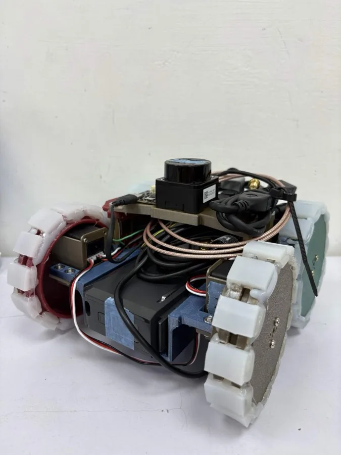
In their words
Navigation and victim identification in unknown, resource-constrained environments present significant challenges for small-scale autonomous robots. This paper presents an integrated solution featuring a dual-compute architecture centered on the NVIDIA Jetson Orin NX and a Raspberry Pi 5 for distributed vision processing. We utilize the ROS2 Jazzy framework to implement a robust navigation stack that incorporates SLAM-based mapping (slam_toolbox) and EKF-fused odometry to overcome the limitations of skid-steering kinematics. To address the difficulty of victim identification under variable lighting conditions, we introduce a hybrid vision pipeline that uses Canny edge-based HOG feature extraction and SVM classification, supplemented by a four-quadrant geometric validation algorithm to ensure high precision. Through an isolated power distribution architecture, we successfully mitigated voltage-drop issues, resulting in a stable and reliable platform capable of autonomous exploration and high-fidelity rescue kit deployment in complex maze environments.
Team description paper
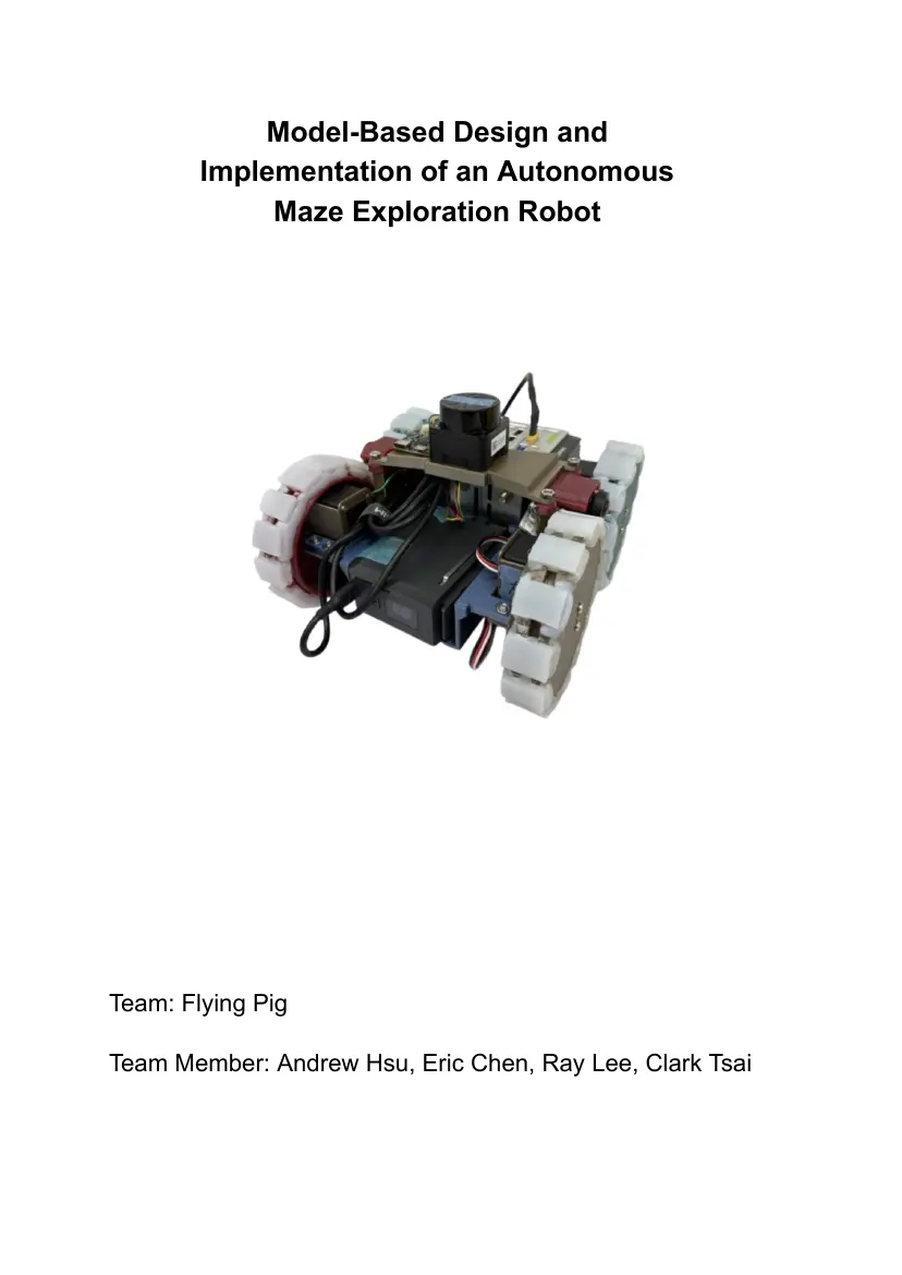
Show the remaining 17 pages
Read the text of this document — 4370 words
Model-Based Design and
Implementation of an Autonomous
Maze Exploration Robot
Team: Flying Pig
Team Member: Andrew Hsu, Eric Chen, Ray Lee, Clark Tsai
Abstract:
Navigation and victim identification in unknown,
resource-constrained environments present significant
challenges for small-scale autonomous robots. This paper
presents an integrated solution featuring a dual-compute
architecture centered on the NVIDIA Jetson Orin NX and a
Raspberry Pi 5 for distributed vision processing. We utilize
the ROS2 Jazzy framework to implement a robust navigation
stack that incorporates SLAM-based mapping (slam_toolbox)
and EKF-fused odometry to overcome the limitations of
skid-steering kinematics. To address the difficulty of victim
identification under variable lighting conditions, we introduce
a hybrid vision pipeline that uses Canny edge-based HOG
feature extraction and SVM classification, supplemented by a
four-quadrant geometric validation algorithm to ensure high
precision. Through an isolated power distribution
architecture, we successfully mitigated voltage-drop issues,
resulting in a stable and reliable platform capable of
autonomous exploration and high-fidelity rescue kit
deployment in complex maze environments.
1. Introduction:
1.1 Team
Andrew Hsu
Electrical system engineer and machanical engineer. Andrew coordinated the
team collaboration while contributing to the programming efforts. His dual role
ensured the project did not go over budget.
Eric Chen
Lead programmer, controller system engineer, and navigation system
designer. Eric leads the development of the robot's control algorithms and navigation
systems, leveraging his extensive experience in programming, mathematics, systems
design, and ROS.
Ray Lee
Mechanical engineer and materials engineer. Drawing from his background in
mechanical engineering and materials science, Ray was responsible for the
structural design and manufacturing of the robot.
Clark Tsai
Programmer and vision system engineer. Clark designed and implemented
integrated machine-vision algorithms. He also coordinated the team's timeline,
ensuring the project stayed on track.
1.2 The Challenge:
Our robot is designed to overcome four critical challenges presented by the
RoboCup Rescue Maze environment:
● Navigating Complex Terrains: The maze contains debris and speed bumps
that demand high-torque movement. We utilize four Feetech ST3215 serial
bus servos, which provide precise odometry feedback (position and load),
ensuring the robot can maneuver accurately even when encountering
friction or obstacles.
● Resource-Constrained Computing: The maze requires simultaneous
execution of SLAM, obstacle avoidance, and machine learning. To prevent
the computational bottlenecks experienced in earlier prototypes, we
transitioned to a Dual-Compute Architecture. The reComputer mini (Jetson
Orin NX) handles global path planning and SLAM, while the Raspberry Pi 5
facilitates visual processing, ensuring high-frequency control loops.
● Localization and Mapping: Without external positioning, our robot relies on
sensor fusion between the Adafruit BNO055 IMU and 360-degree LiDAR.
By positioning these sensors at the exact center of rotation atop the
chassis, we minimize kinematic uncertainty and optimize the accuracy of
our recursive state estimation.
● Victim Identification under Variable Lighting: Our vision system uses the
OpenMV RT1062 camera. Through OpenCV-based ROI extraction and a
trained SVM classifier, we successfully identify "letter victims" (Psi, Phi,
Omega). To handle the challenge of fluctuating lighting, we prioritize training
and inference on edge frames (using Canny edge detection), which offers
superior robustness compared to standard RGB imaging.
2. Model-Based Systems Engineering -
Plans and Milestones:
2.1 Overall Project Plan and Checkpoints
To address the challenges of the RoboCup Rescue Maze, our
development follows an agile Model-Based Systems Engineering (MBSE)
approach.
Date Milestone / Checkpoint Member
2026/02/20 Design & Architecture: Completed All
structural CAD design and initial
selection of the Raspberry Pi 5 as the
primary compute platform.
2026/03/15 Navigation Development: Integrated Eric
LiDAR and IMU modules. Developed
initial SLAM and path-planning stacks
on the Pi 5.
2026/04/28 Strategic Pivot: Team meeting All
concluded, with migration of the primary
control stack to NVIDIA Jetson Orin NX
to leverage GPU acceleration for SLAM
and AI inference.
2026/05/30 Hardware Arrival & Migration: Received Ray, Andrew
the reComputer mini J4012. Initiated
software migration from Pi 5 to Orin NX,
maintaining the Pi 5 as a dedicated
vision testing node.
2026/06/10 System Integration & Stability: Andrew, Ray
Consolidated the entire vision pipeline
into the Orin NX. Implemented
hardware binding for consistent
peripheral addressing.
2026/06/15 Performance Tuning:Fine-tuned SLAM All
and Nav2 parameters, specifically
optimizing path planning for narrow
maze corridors.
2026/06/20 Final System Validation: Completed All
end-to-end integration testing of
autonomous exploration and victim
identification.
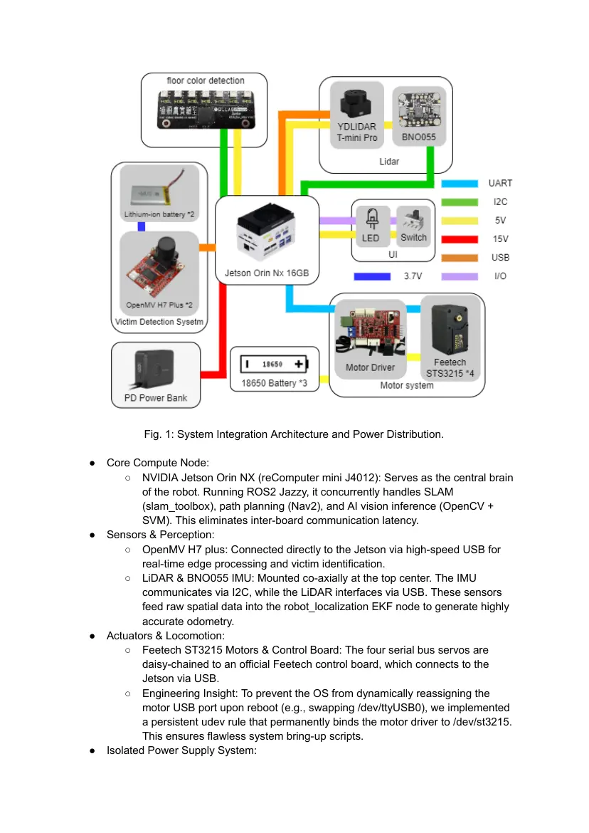
2.2 System Integration Architecture
Our robot utilizes a highly modular yet centralized integration architecture.
Unlike our previous iteration, which struggled with distributed bottlenecks, the 2026
design focuses on centralized computation and isolated power distribution to
maximize reliability and data throughput.
Fig. 1: System Integration Architecture and Power Distribution.
● Core Compute Node:
○ NVIDIA Jetson Orin NX (reComputer mini J4012): Serves as the central brain
of the robot. Running ROS2 Jazzy, it concurrently handles SLAM
(slam_toolbox), path planning (Nav2), and AI vision inference (OpenCV +
SVM). This eliminates inter-board communication latency.
● Sensors & Perception:
○ OpenMV H7 plus: Connected directly to the Jetson via high-speed USB for
real-time edge processing and victim identification.
○ LiDAR & BNO055 IMU: Mounted co-axially at the top center. The IMU
communicates via I2C, while the LiDAR interfaces via USB. These sensors
feed raw spatial data into the robot_localization EKF node to generate highly
accurate odometry.
● Actuators & Locomotion:
○ Feetech ST3215 Motors & Control Board: The four serial bus servos are
daisy-chained to an official Feetech control board, which connects to the
Jetson via USB.
○ Engineering Insight: To prevent the OS from dynamically reassigning the
motor USB port upon reboot (e.g., swapping /dev/ttyUSB0), we implemented
a persistent udev rule that permanently binds the motor driver to /dev/st3215.
This ensures flawless system bring-up scripts.
● Isolated Power Supply System:
○ Logic Power (PD Power Bank): Directly supplies clean, 100% stable power to
the Jetson Orin NX via USB-C Power Delivery, ensuring the logic circuits are
immune to mechanical voltage spikes.
○ Actuator Power (18650 Battery Pack): A dedicated 3-cell 18650 battery pack
powers the motor control board exclusively. This physical isolation completely
eliminates the sudden voltage drops that previously caused the main compute
board to reboot during sudden motor acceleration.
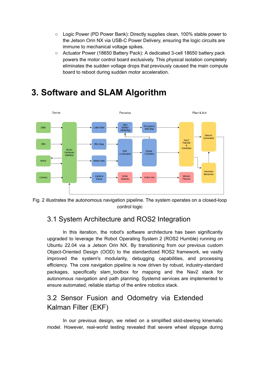
3. Software and SLAM Algorithm
Fig. 2 illustrates the autonomous navigation pipeline. The system operates on a closed-loop
control logic
3.1 System Architecture and ROS2 Integration
In this iteration, the robot's software architecture has been significantly
upgraded to leverage the Robot Operating System 2 (ROS2 Humble) running on
Ubuntu 22.04 via a Jetson Orin NX. By transitioning from our previous custom
Object-Oriented Design (OOD) to the standardized ROS2 framework, we vastly
improved the system's modularity, debugging capabilities, and processing
efficiency. The core navigation pipeline is now driven by robust, industry-standard
packages, specifically slam_toolbox for mapping and the Nav2 stack for
autonomous navigation and path planning. Systemd services are implemented to
ensure automated, reliable startup of the entire robotics stack.
3.2 Sensor Fusion and Odometry via Extended
Kalman Filter (EKF)
In our previous design, we relied on a simplified skid-steering kinematic
model. However, real-world testing revealed that severe wheel slippage during
turns, inherent to the four-wheel differential drive mechanism, caused significant
inaccuracies in pure wheel odometry.
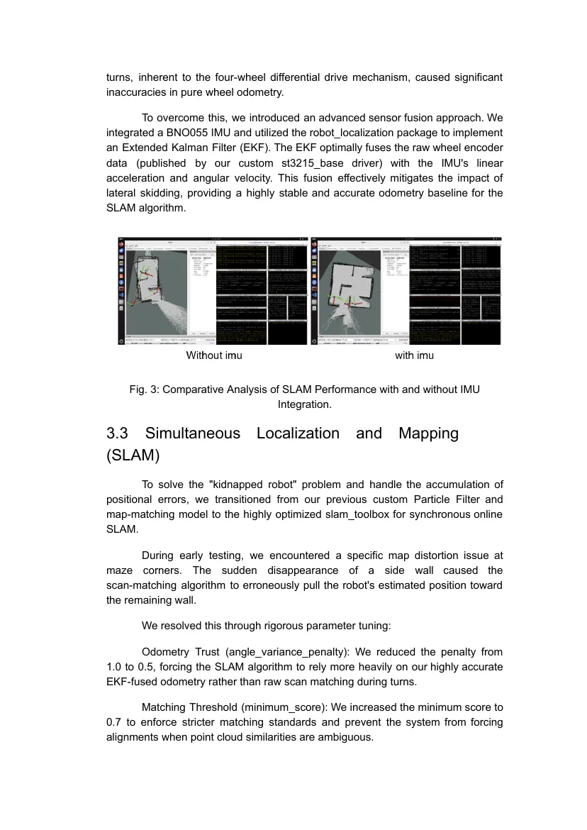
To overcome this, we introduced an advanced sensor fusion approach. We
integrated a BNO055 IMU and utilized the robot_localization package to implement
an Extended Kalman Filter (EKF). The EKF optimally fuses the raw wheel encoder
data (published by our custom st3215_base driver) with the IMU's linear
acceleration and angular velocity. This fusion effectively mitigates the impact of
lateral skidding, providing a highly stable and accurate odometry baseline for the
SLAM algorithm.
Fig. 3: Comparative Analysis of SLAM Performance with and without IMU
Integration.
3.3 Simultaneous Localization and Mapping
(SLAM)
To solve the "kidnapped robot" problem and handle the accumulation of
positional errors, we transitioned from our previous custom Particle Filter and
map-matching model to the highly optimized slam_toolbox for synchronous online
SLAM.
During early testing, we encountered a specific map distortion issue at
maze corners. The sudden disappearance of a side wall caused the
scan-matching algorithm to erroneously pull the robot's estimated position toward
the remaining wall.
We resolved this through rigorous parameter tuning:
Odometry Trust (angle_variance_penalty): We reduced the penalty from
1.0 to 0.5, forcing the SLAM algorithm to rely more heavily on our highly accurate
EKF-fused odometry rather than raw scan matching during turns.
Matching Threshold (minimum_score): We increased the minimum score to
0.7 to enforce stricter matching standards and prevent the system from forcing
alignments when point cloud similarities are ambiguous.
3.4 Navigation and Path Planning (Nav2)
Navigating the RoboCup Rescue Maze presents extreme spatial
constraints, with 30x30 cm tiles leaving as little as 5 cm of clearance for the robot.
Previously, we utilized a topological Depth-First Search (DFS) and a Pure Pursuit
controller. To achieve smoother and more reliable obstacle avoidance, we have
fully integrated the Nav2 stack.
Costmap and Footprint Configuration:
● Precise footprint configuration is critical to preventing the robot from getting
stuck. We decoupled the global and local footprints:
● Global Costmap: Configured to a 16x16 cm footprint to prevent "start
occupied" or "no valid path found" errors during global trajectory
generation.
● Local Costmap: Configured to a broader 18.2x18.2 cm footprint to ensure
the local trajectory provides sufficient clearance for the robot's physical
dimensions during sharp turns.
Path Planner Optimization (SmacPlanner2D):
Initially, we implemented the SmacPlannerLattice. However, the kinematic
constraints of the lattice planner combined with the extreme narrowness of the
maze frequently resulted in "no valid path" errors. Increasing the inflation radius
caused start failures, while decreasing it caused the robot to scrape the walls.
To resolve this, we shifted our global planner to SmacPlanner2D, an
A*-based planner. The 2D planner proved much more adaptable to tight corridors.
By increasing the inflation_radius to 1.2, we successfully ensured that the
generated paths remained perfectly centered within the corridors. Furthermore, by
enabling the allow_start_in_occupied: true parameter, the SmacPlanner2D can still
calculate valid escape paths even if the robot's initial position slightly overlaps with
the heavily inflated obstacle zones, drastically reducing maneuver failures.
3.5 Autonomous Exploration
To complete the autonomous capabilities, we replaced our previous manual
DFS branching logic with the frontier_explorer package. This allows the robot to
dynamically identify unexplored regions (frontiers) on the occupancy grid
generated by slam_toolbox, continuously publishing new navigation goals to Nav2
until the entire maze is successfully mapped and explored.
4. Victim Identification System:
4.1 Training and Testing
To achieve high-accuracy victim identification and streamline our hardware
layout, we ultimately consolidated our entire vision system onto our main
computing unit, the NVIDIA Jetson Orin NX (16GB).
During the development phase, the vision algorithms were initially
prototyped and rigorously tested on a Raspberry Pi 5 paired with a Logitech USB
Camera. This decoupled testing phase was crucial; it allowed us to independently
train, tune, and validate our machine learning models and OpenCV pipelines
without interfering with the ongoing development of the navigation and SLAM
stack.
Once the vision algorithms were proven stable and accurate, the entire
pipeline was successfully migrated to the Jetson Orin NX. This final centralized
architecture eliminates inter-board communication latency, reduces hardware
complexity, and leverages the Jetson's superior processing power to execute
SLAM, navigation, and AI vision concurrently without performance bottlenecks.
4.2 Image Preprocessing and ROI Extraction (OpenCV)
To efficiently locate candidate victims within the maze, the live camera feed
undergoes a strict preprocessing pipeline using the OpenCV library before any
classification occurs:
● Grayscale Conversion & Gaussian Blur
○ The raw image is grayscaled and blurred to eliminate background
noise and smooth out pixel variations.
● Canny Edge Detection
○ We use the Canny edge detector to detect salient contours.
● ROI Cropping & Area Constraints
○ Initially, the system suffered from severe background interference,
where small debris was detected as candidate Regions of Interest
(ROIs). We resolved this by implementing OpenCV bounding-box area
constraints, effectively filtering out extremely small objects and
cropping only valid victim-sized regions for further inference.
● Engineering Insight
○ During extensive testing, we discovered that training and inference on
Edge Frames is significantly more stable and robust than using raw
RGB images. Edge frames are far less susceptible to lighting
variations and shadows within the maze, ensuring highly consistent
feature extraction
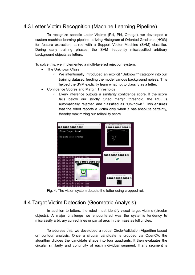
4.3 Letter Victim Recognition (Machine Learning Pipeline)
To recognize specific Letter Victims (Psi, Phi, Omega), we developed a
custom machine learning pipeline utilizing Histogram of Oriented Gradients (HOG)
for feature extraction, paired with a Support Vector Machine (SVM) classifier.
During early training phases, the SVM frequently misclassified arbitrary
background objects as letters.
To solve this, we implemented a multi-layered rejection system.
● The Unknown Class
○ We intentionally introduced an explicit "Unknown" category into our
training dataset, feeding the model various background noises. This
helped the SVM explicitly learn what not to classify as a letter.
● Confidence Scores and Margin Thresholds
○ Every inference outputs a similarity confidence score. If the score
falls below our strictly tuned margin threshold, the ROI is
automatically rejected and classified as "Unknown.” This ensures
that the robot reports a victim only when it has absolute certainty,
thereby maximizing our reliability score.
Fig. 4: The vision system detects the letter using cropped roi.
4.4 Target Victim Detection (Geometric Analysis)
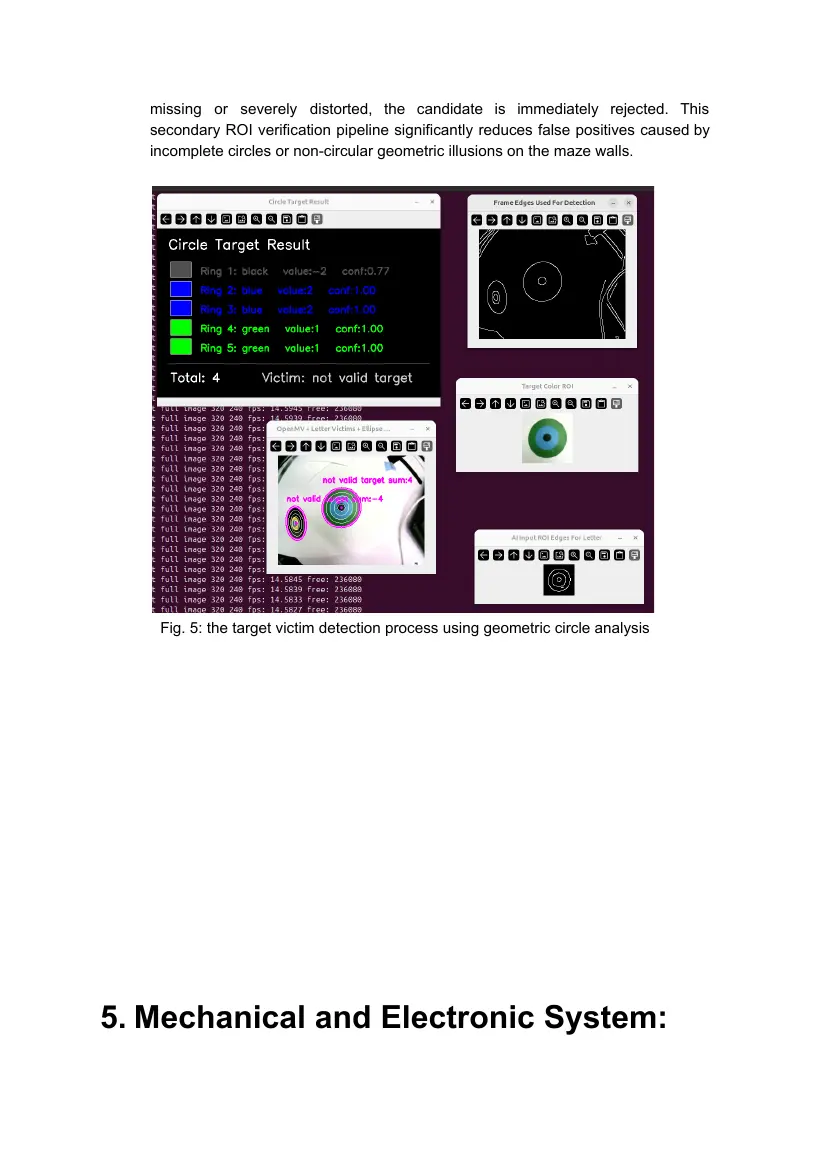
In addition to letters, the robot must identify visual target victims (circular
objects). A major challenge we encountered was the system's tendency to
misclassify arbitrary curved lines or partial arcs in the maze as full circles.
To address this, we developed a robust Circle-Validation Algorithm based
on contour analysis. Once a circular candidate is cropped via OpenCV, the
algorithm divides the candidate shape into four quadrants. It then evaluates the
circular similarity and continuity of each individual segment. If any segment is
missing or severely distorted, the candidate is immediately rejected. This
secondary ROI verification pipeline significantly reduces false positives caused by
incomplete circles or non-circular geometric illusions on the maze walls.
Fig. 5: the target victim detection process using geometric circle analysis
5. Mechanical and Electronic System:
To optimize reliability and space utilization within the strict 30x30 cm maze
constraints, we consolidated our mechanical and electronic systems into a highly
integrated, modular chassis. All structural components were custom-designed and
validated using 3D CAD software before manufacturing.
5.1 Core Compute and Isolated Power Supply
At the heart of our robot is the reComputer Mini J4012 (powered by NVIDIA
Jetson Orin NX). In previous iterations, we encountered critical system instability:
high current draw during motor startup caused severe voltage drops, leading to
unexpected reboots of the main compute board.
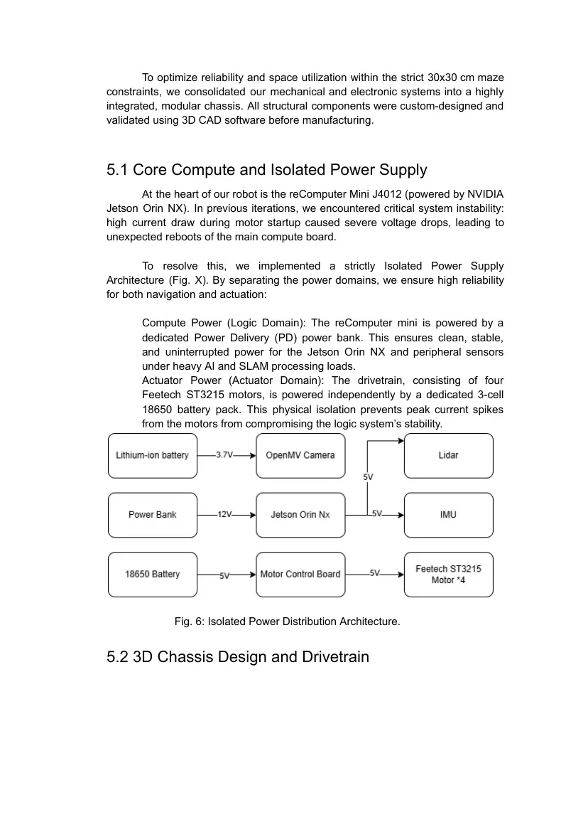
To resolve this, we implemented a strictly Isolated Power Supply
Architecture (Fig. X). By separating the power domains, we ensure high reliability
for both navigation and actuation:
Compute Power (Logic Domain): The reComputer mini is powered by a
dedicated Power Delivery (PD) power bank. This ensures clean, stable,
and uninterrupted power for the Jetson Orin NX and peripheral sensors
under heavy AI and SLAM processing loads.
Actuator Power (Actuator Domain): The drivetrain, consisting of four
Feetech ST3215 motors, is powered independently by a dedicated 3-cell
18650 battery pack. This physical isolation prevents peak current spikes
from the motors from compromising the logic system’s stability.
Fig. 6: Isolated Power Distribution Architecture.
5.2 3D Chassis Design and Drivetrain
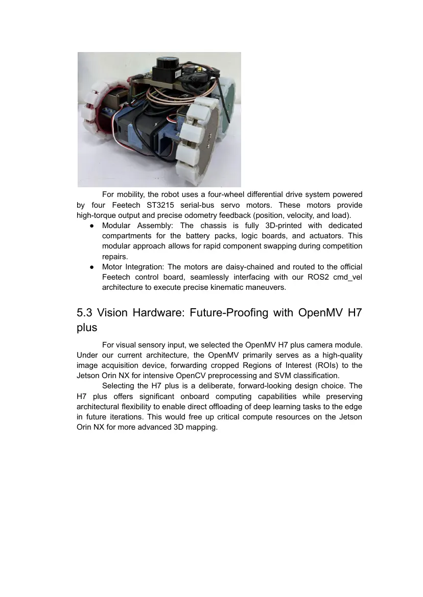
For mobility, the robot uses a four-wheel differential drive system powered
by four Feetech ST3215 serial-bus servo motors. These motors provide
high-torque output and precise odometry feedback (position, velocity, and load).
● Modular Assembly: The chassis is fully 3D-printed with dedicated
compartments for the battery packs, logic boards, and actuators. This
modular approach allows for rapid component swapping during competition
repairs.
● Motor Integration: The motors are daisy-chained and routed to the official
Feetech control board, seamlessly interfacing with our ROS2 cmd_vel
architecture to execute precise kinematic maneuvers.
5.3 Vision Hardware: Future-Proofing with OpenMV H7
plus
For visual sensory input, we selected the OpenMV H7 plus camera module.
Under our current architecture, the OpenMV primarily serves as a high-quality
image acquisition device, forwarding cropped Regions of Interest (ROIs) to the
Jetson Orin NX for intensive OpenCV preprocessing and SVM classification.
Selecting the H7 plus is a deliberate, forward-looking design choice. The
H7 plus offers significant onboard computing capabilities while preserving
architectural flexibility to enable direct offloading of deep learning tasks to the edge
in future iterations. This would free up critical compute resources on the Jetson
Orin NX for more advanced 3D mapping.
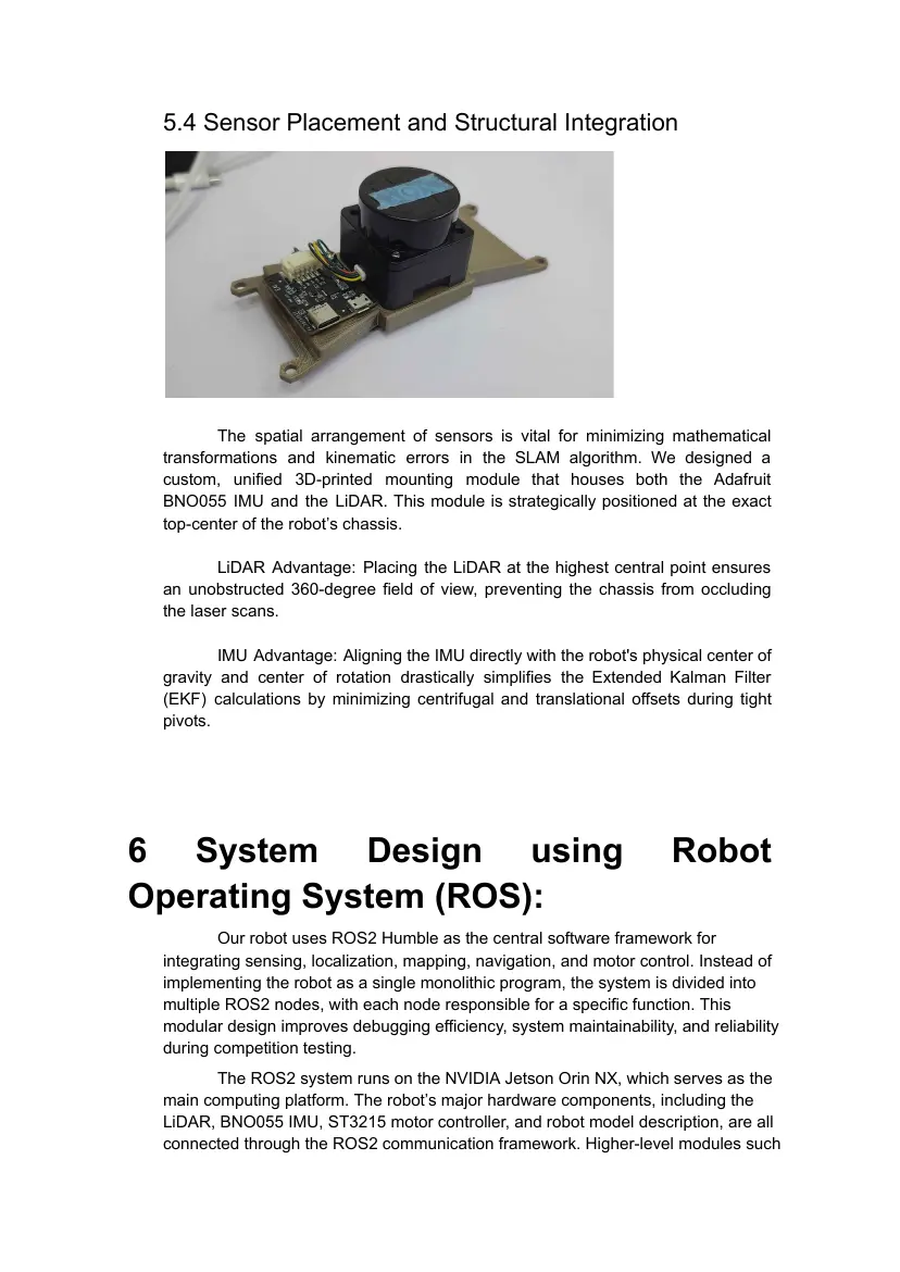
5.4 Sensor Placement and Structural Integration
The spatial arrangement of sensors is vital for minimizing mathematical
transformations and kinematic errors in the SLAM algorithm. We designed a
custom, unified 3D-printed mounting module that houses both the Adafruit
BNO055 IMU and the LiDAR. This module is strategically positioned at the exact
top-center of the robot’s chassis.
LiDAR Advantage: Placing the LiDAR at the highest central point ensures
an unobstructed 360-degree field of view, preventing the chassis from occluding
the laser scans.
IMU Advantage: Aligning the IMU directly with the robot's physical center of
gravity and center of rotation drastically simplifies the Extended Kalman Filter
(EKF) calculations by minimizing centrifugal and translational offsets during tight
pivots.
6 System Design using Robot
Operating System (ROS):
Our robot uses ROS2 Humble as the central software framework for
integrating sensing, localization, mapping, navigation, and motor control. Instead of
implementing the robot as a single monolithic program, the system is divided into
multiple ROS2 nodes, with each node responsible for a specific function. This
modular design improves debugging efficiency, system maintainability, and reliability
during competition testing.
The ROS2 system runs on the NVIDIA Jetson Orin NX, which serves as the
main computing platform. The robot’s major hardware components, including the
LiDAR, BNO055 IMU, ST3215 motor controller, and robot model description, are all
connected through the ROS2 communication framework. Higher-level modules such
as EKF localization, SLAM, and Nav2 navigation then use this sensor and actuator
information to perform autonomous maze exploration.
6.1 ROS2 Software Architecture
The software architecture is organized into several functional layers: sensor
input, robot state estimation, mapping, navigation, and motor execution.
At the sensor layer, the LiDAR driver publishes 2D laser scan data for
mapping and obstacle detection. The BNO055 IMU driver publishes orientation,
angular velocity, and acceleration data. The motor base driver communicates with the
ST3215 serial-bus motors and provides wheel-odometry information.
At the localization layer, the “robot_localization” EKF node fuses wheel
odometry and IMU data to produce a more stable estimate of the robot’s motion. This
is necessary because the four-wheel differential-drive mechanism may experience
wheel slippage during turning, especially in narrow maze corridors.
At the mapping layer, “slam_toolbox” receives LiDAR scan data and fused
odometry to construct an occupancy grid map of the maze. The SLAM system also
maintains the relationship between the global map frame and the local odometry
frame.
At the navigation layer, Nav2 uses the map, costmaps, robot footprint,
planner, controller, and recovery behaviors to generate safe movement commands.
These velocity commands are sent to the ST3215 base driver, which converts them
into motor commands for physical movement.
6.2 ROS2 Node Responsibilities
The complete robot system is composed of the following main ROS2 components:
Component Main Responsibility
LiDAR Driver Publishes 2D laser scan data for SLAM and obstacle detection
ST3215 Base Driver Converts velocity commands into motor commands and
publishes wheel odometry
BNO055 IMU Driver Publishes orientation, angular velocity, and acceleration data
Static TF Publisher Defines the fixed transform between the robot base frame and
the IMU frame
Robot State Publisher Publishes the robot’s URDF-based frame structure
EKF Localization Node Fuses wheel odometry and IMU data into stable odometry
slam_toolbox Builds the maze map and provides SLAM-based localization
Nav2 Stack Performs global planning, local control, obstacle avoidance, and
navigation
This separation allows each subsystem to be tested independently. For
example, the motor driver can be tested using manual velocity commands, while the
LiDAR and SLAM system can be tested without running the full navigation stack. This
modularity makes debugging faster and reduces the risk of system-wide failure.
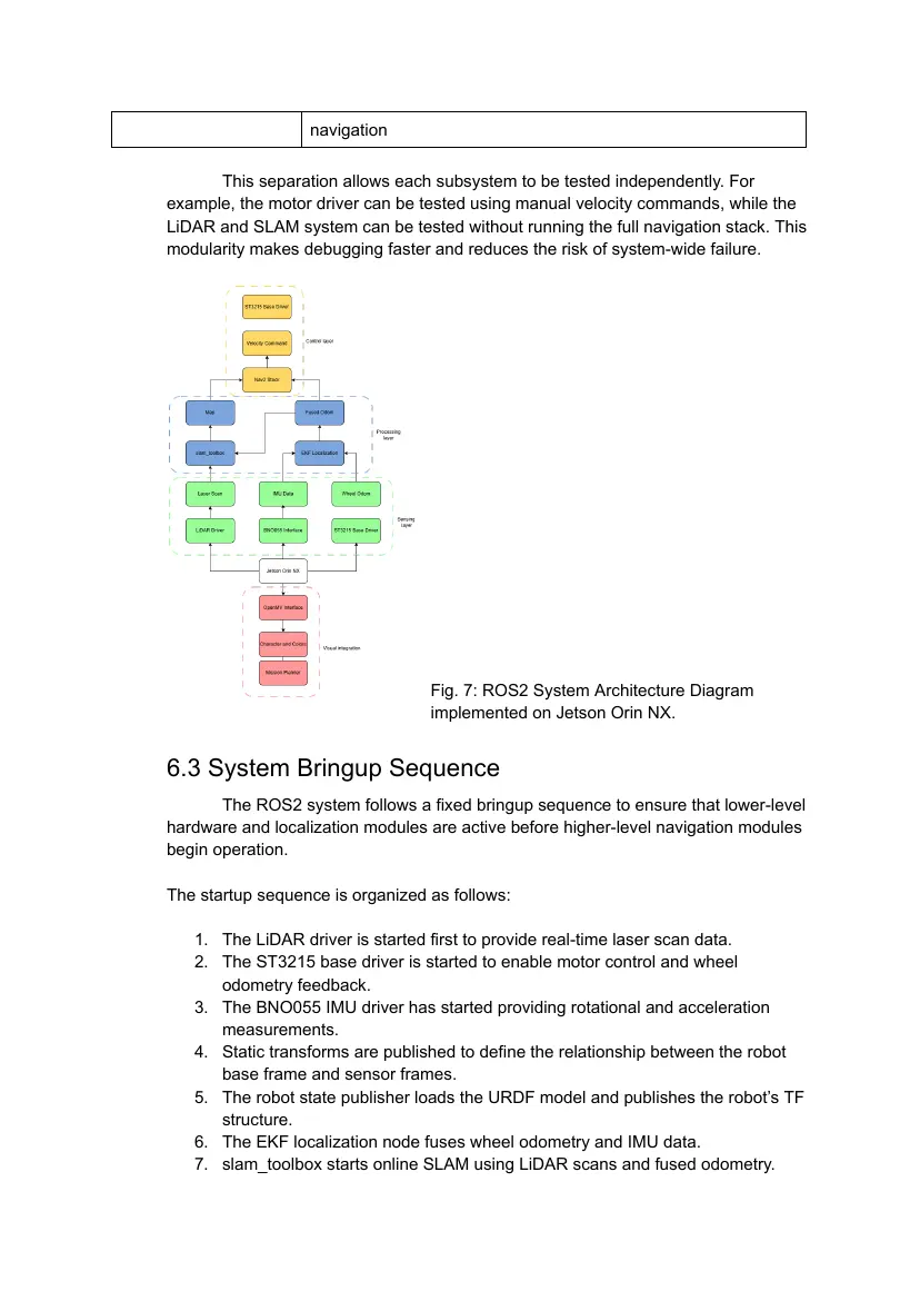
Fig. 7: ROS2 System Architecture Diagram
____________________________implemented on Jetson Orin NX.
6.3 System Bringup Sequence
The ROS2 system follows a fixed bringup sequence to ensure that lower-level
hardware and localization modules are active before higher-level navigation modules
begin operation.
The startup sequence is organized as follows:
1. The LiDAR driver is started first to provide real-time laser scan data.
2. The ST3215 base driver is started to enable motor control and wheel
odometry feedback.
3. The BNO055 IMU driver has started providing rotational and acceleration
measurements.
4. Static transforms are published to define the relationship between the robot
base frame and sensor frames.
5. The robot state publisher loads the URDF model and publishes the robot’s TF
structure.
6. The EKF localization node fuses wheel odometry and IMU data.
7. slam_toolbox starts online SLAM using LiDAR scans and fused odometry.
8. Nav2 starts after the map, odometry, and TF frames are available.
This order is important because SLAM and Nav2 depend on valid sensor
data, odometry, and coordinate transforms. Starting the system in this sequence
reduces initialization errors and improves the reliability of autonomous navigation.
6.4 Topic-Based Communication
ROS2 topics are used to exchange real-time data between different modules.
The main data flow of the robot is shown below:
Data Source Used By Purpose
Laser scan data LiDAR driver slam_toolbox, Nav2 Mapping and
costmap obstacle detection
IMU data BNO055 driver EKF localization Rotation and
acceleration
correction
Wheel odometry ST3215 base driver EKF localization Motion estimation
Fused odometry EKF localization slam_toolbox, Nav2 Stable localization
input
Occupancy grid map slam_toolbox Nav2, RViz Maze mapping and
path planning
Velocity command Nav2 controller ST3215 base driver Motor control
TF transforms robot_state_publish All navigation Coordinate frame
er, EKF, SLAM modules alignment
LiDAR -> Laser Scan -> SLAM Map
IMU + Wheel Odometry -> EKF -> Fused Odometry
Map + Fused Odometry -> Nav2 -> Velocity Command -> ST3215
Motors
With this topic-based structure, each subsystem can remain independent
while still contributing to the robot's overall autonomous behavior.
7 Experimentation and Improvement
Made:
7.1 System Architecture Migration (From Pi 5 to Orin NX)
Initially, our software stack and vision pipeline were developed on the
Raspberry Pi 5. However, as we integrated more complex machine learning models
for victim identification and high-frequency SLAM processing, we identified a critical
performance bottleneck: the Pi 5 could not concurrently handle heavy AI inference
and real-time navigation without latency spikes.
In our April 28th architecture review, we concluded that a significant
performance upgrade was necessary. We decided to transition to the NVIDIA Jetson
Orin NX (16GB) architecture. This migration was a calculated engineering decision to
leverage GPU acceleration for parallel AI processing, ensuring that the navigation
stack (SLAM/Nav2) remains completely isolated from the vision pipeline's
computational demands.
7.2 Mechanical Design Optimization for Component
Integration
The integration of the Jetson Orin NX and its extension board posed a
significant structural challenge due to the maze’s strict 30x30 cm footprint and 25 cm
height limit. The original Pi 5-based chassis was insufficient for the increased
footprint of the new core module.
Engineering Improvements:
● Chassis Reconfiguration (June 5-6): During initial assembly, we identified
structural instabilities in the mounting of the multi-layer controller boards. We
replaced the original mounting hardware with heavy-duty standoffs and
screws, ensuring the Orin NX could withstand high-vibration maneuvers on
rough terrain.
● In-Wheel Motor Integration (June 7): To maximize the limited internal chassis
space for the Orin NX, we completely redesigned our drivetrain. By modifying
the wheel geometry to allow for in-wheel motor integration, we significantly
reduced the overall chassis profile.
● Power Distribution Optimization: With the additional space gained from the
motor redesign, we successfully reallocated the 18650 battery pack to the
side of the Jetson Orin NX. This lowered the center of gravity and enabled the
installation of a dedicated PD-capable power bank, ensuring that the compute
unit is powered independently of the actuators and successfully eliminating
the voltage drop issues encountered in earlier prototypes.
7.3 Navigation Algorithm Iteration: From Lattice to
SmacPlanner2D
During our navigation development, we encountered a significant limitation
with the SmacPlannerLattice planner in the RoboCup maze. Due to the extremely
narrow passages (5 cm clearance), the lattice planner frequently produced "no valid
path" or "start occupied" errors when inflation parameters were tuned to prevent wall
collisions.
● Experimentation: We conducted a series of tests in the physical maze,
varying the inflation radius from 0.8 to 1.2. We found that while larger inflation
radii effectively centered the robot in the corridors, they also caused the
planner to erroneously treat the robot's current position as an obstacle ("start
occupied").
● Result (The Improvement): We migrated to SmacPlanner2D (A*-based). By
setting allow_start_in_occupied: true and tuning the inflation_radius to 1.2,
the robot successfully generated optimal paths in the center of narrow lanes.
This shift drastically improved our path planning success rate in cluttered
environments and eliminated the oscillatory behavior observed in earlier
iterations.
7.4 Sensor Fusion and SLAM Robustness
In early testing, raw LiDAR-based SLAM exhibited "map drifting" whenever
the robot rotated in corners, as the disappearance of walls caused the scan-matching
algorithm to lose its spatial reference point.
● Experimentation: We observed that the slam_toolbox was overly reliant on
scan-matching, which is prone to noise in feature-poor corners. We tested the
integration of an Extended Kalman Filter (EKF) using the robot_localization
package to fuse wheel odometry with the BNO055 IMU.
● Result (The Improvement): We adjusted the angle_variance_penalty from 1.0
to 0.5 and set a minimum_score of 0.7. This forced the SLAM system to
prioritize the IMU-corrected odometry over raw scan matches when the
likelihood score was ambiguous. As shown in our field test data (Fig. X), this
fusion approach maintained linear wall tracking even during high-yaw
maneuvers, resolving the map distortion issue.
7.5 Vision System: Reducing False Positives
Our initial SVM-based vision pipeline suffered from frequent false-positive
detections, where background geometry was incorrectly flagged as victim letters.
● Experimentation: We tested the model against various background images,
including structural aluminum extrusions and debris. We hypothesized that
the SVM needed a clear "background" reference.
● Result (The Improvement): We introduced a multi-layered rejection pipeline:
○ "Unknown" Category: By training the SVM with non-victim background
noise, the model learned to reject features that did not resemble our
target letters.
○ Geometry-based Validation: For circular targets, we implemented a
four-quadrant symmetry verification. By programmatically checking the
continuity of circular contours, we filtered out shapes that only
resembled circles (e.g., arcs or broken lines), thereby significantly
improving target detection precision during real-world trials.
20 pages, rendered as images so they load quickly. The text above is the document's own, extracted from the PDF.
Engineering journal
Shown as the original PDF, because this one is smaller that way and its text stays selectable and searchable.