Delta

Maze league · Australia · RoboCup 2026

Document register

  1. Poster1 pagePublished
  2. Presentation videoYouTubePublished
  3. Bill of materials5 pagesPublished
  4. Team description paperNot shared
  5. Engineering journalNot shared
  6. Source code34 KB · GitHubPublished

Sharing each document is the team's decision. “Not shared” means this team chose not to publish it, or did not submit one — not that it is missing from the archive.
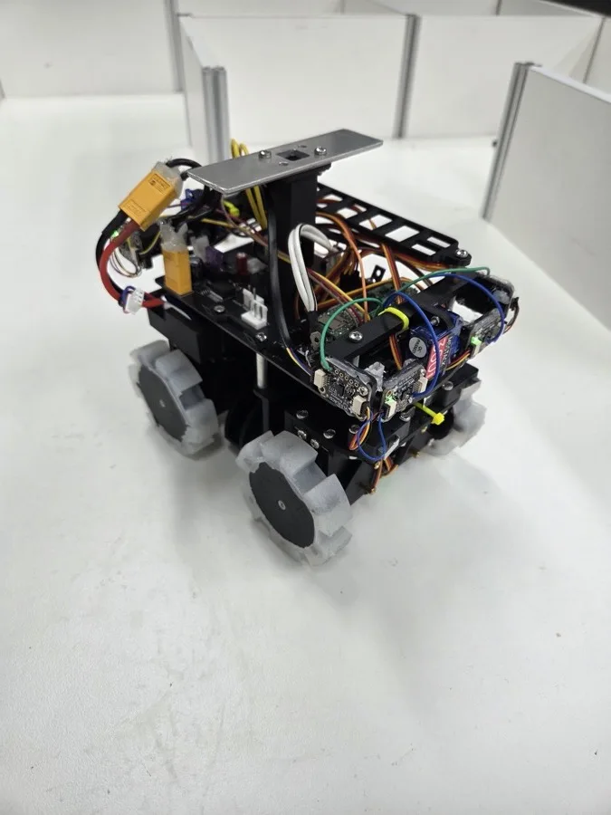
Delta's robot
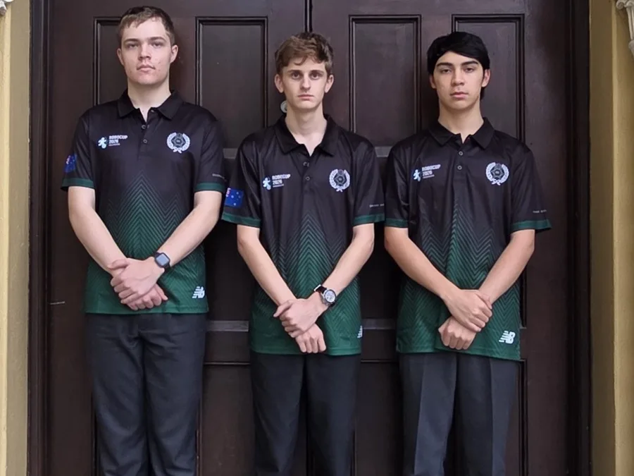
The Delta team

In their words

Our robot’s main capabilities include the ability to correct its alignment in the maze by using its two ToF sensors on each side to determine its skew in the maze and correct for this. It also incorporates a custom pivoting ToF sensor system for the front and rear ToF sensors allowing the sensors to always look flat at the walls even when training over bumps and when the robot will not be level with the ground.

Poster
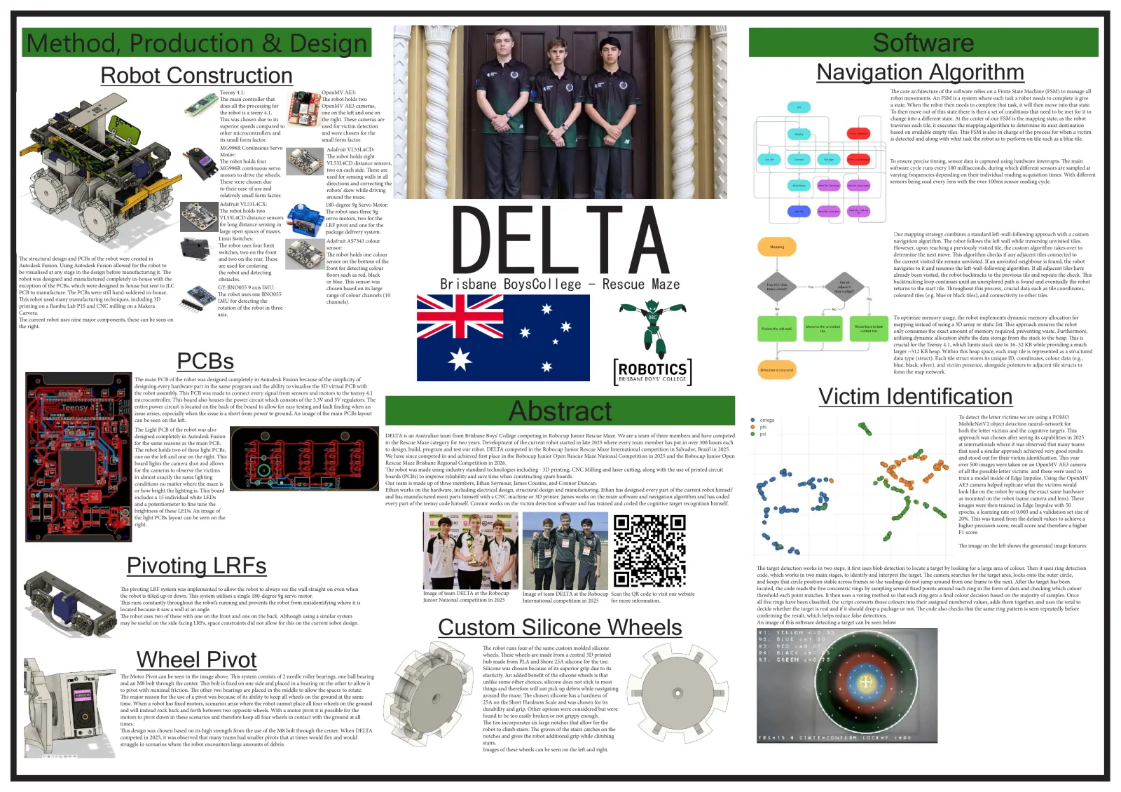
Read the text of this document — 2138 words
Method, Production & Design                                                                                                                                                                                                                                                                                                                                                         Software
                                    Robot Construction                                                                                                                                                                                                                                                                                                       Navigation Algorithm
                                                                                        Teensy 4.1:                                   OpenMV AE3:                                                                                                                                                                                                                                              The core architecture of the software relies on a Finite State Machine (FSM) to manage all
                                                                                        The main controller that                      The robot holds two                                                                                                                                                                                                                                      robot movements. An FSM is a system where each task a robot needs to complete is give
                                                                                        does all the processing for                   OpenMV AE3 cameras,                                                                                                                                                                                                                                      a state. When the robot then needs to complete that task, it will then move into that state.
                                                                                        the robot is a teeny 4.1.                     one on the left and one on                                                                                                                                                                                                                               To then move out of this state there is then a set of conditions that need to be met for it to
                                                                                        This was chosen due to its                    the right. These cameras are                                                                                                                                                                                                                             change into a different state. At the center of our FSM is the mapping state; as the robot
                                                                                        superior speeds compared to                   used for victim detection                                                                                                                                                                                                                                traverses each tile, it executes the mapping algorithm to determine its next destination
                                                                                        other microcontrollers and                    and were chosen for the                                                                                                                                                                                                                                  based on available empty tiles. This FSM is also in charge of the process for when a victim
                                                                                        its small form factor.                        small form factor.                                                                                                                                                                                                                                       is detected and along with what task the robot as to perform on tile such as a blue tile.
                                                                                        MG996R Continuous Servo                          Adafruit VL53L4CD:
                                                                                        Motor:                                           The robot holds eight
                                                                                        The robot holds four                             VL53L4CD distance sensors,                                                                                                                                                                                                                            To ensure precise timing, sensor data is captured using hardware interrupts. The main
                                                                                        MG996R continuous servo                          two on each side. These are                                                                                                                                                                                                                           software cycle runs every 100 milliseconds, during which different sensors are sampled at
                                                                                        motors to drive the wheels.                      used for sensing walls in all                                                                                                                                                                                                                         varying frequencies depending on their individual reading acquisition times. With different
                                                                                        These were chosen due                            directions and correcting the                                                                                                                                                                                                                         sensors being read every 5ms with the over 100ms sensor reading cycle.
                                                                                        to their ease of use and                         robots’ skew while driving
                                                                                        relatively small form factor.                    around the maze.
                                                                                         Adafruit VL53L4CX:                             180-degree 9g Servo Motor:

                                                                                                                                                                                                DELTA
                                                                                         The robot holds two                            The robot uses three 9g
                                                                                         VL53L4CD distance sensors                      servo motors, two for the
                                                                                         for long distance sensing in                   LRF pivot and one for the
                                                                                         large open spaces of mazes.                    package delivery system.                                                                                                                                                                                                                                 Our mapping strategy combines a standard left-wall-following approach with a custom
                                                                                        Limit Switches:                                 Adafruit AS7341 colour                                                                                                                                                                                                                                   navigation algorithm. The robot follows the left wall while traversing unvisited tiles.
                                                                                        The robot uses four limit                       sensor:                                                                                                                                                                                                                                                  However, upon reaching a previously visited tile, the custom algorithm takes over to
                                                                                        switches, two on the front                      The robot holds one colour                                                                                                                                                                                                                               determine the next move. This algorithm checks if any adjacent tiles connected to
The structural design and PCBs of the robot were created in                             and two on the rear. These                      sensor on the bottom of the                                                                                                                                                                                                                              the current visited tile remain unvisited. If an unvisited neighbour is found, the robot
Autodesk Fusion. Using Autodesk Fusion allowed for the robot to                         are used for centering                          front for detecting colour                                                                                                                                                                                                                               navigates to it and resumes the left-wall-following algorithm. If all adjacent tiles have
be visualised at any stage in the design before manufacturing it. The                   the robot and detecting                         floors such as red, black                                                                                                                                                                                                                                already been visited, the robot backtracks to the previous tile and repeats the check. This
robot was designed and manufactured completely in-house with the                        obstacles.
exception of the PCBs, which were designed in-house but sent to JLC
PCB to manufacture. The PCBs were still hand-soldered in-house.
                                                                                        GY-BNO055 9 axis IMU:
                                                                                        The robot uses one BNO055
                                                                                                                                        or blue. This sensor was
                                                                                                                                        chosen based on its large                            Brisbane BoysCollege - Rescue Maze                                                                                                                                                                  backtracking loop continues until an unexplored path is found and eventually the robot
                                                                                                                                                                                                                                                                                                                                                                                                 returns to the start tile. Throughout this process, crucial data such as tile coordinates,
                                                                                                                                        range of colour channels (10                                                                                                                                                                                                                             coloured tiles (e.g. blue or black tiles), and connectivity to other tiles.
This robot used many manufacturing techniques, including 3D                             IMU for detecting the                           channels).
printing on a Bambu Lab P1S and CNC milling on a Makera                                 rotation of the robot in three
Carvera.                                                                                axis.
The current robot uses nine major components, these can be seen on                                                                                                                                                                                                                                                                                                                               To optimize memory usage, the robot implements dynamic memory allocation for
the right.                                                                                                                                                                                                                                                                                                                                                                                       mapping instead of using a 3D array or static list. This approach ensures the robot
                                                                                                                                                                                                                                                                                                                                                                                                 only consumes the exact amount of memory required, preventing waste. Furthermore,
                                                                                                                                                                                                                                                                                                                                                                                                 utilizing dynamic allocation shifts the data storage from the stack to the heap. This is
                                                                                                                                                                                                                                                                                                                                                                                                 crucial for the Teensy 4.1, which limits stack size to 16–32 KB while providing a much
                                                                                                                                                                                                                                                                                                                                                                                                 larger ~512 KB heap. Within this heap space, each map tile is represented as a structured

                                                                        PCBs                                                                                                                                                                                                                                                                                                                     data type (struct). Each tile struct stores its unique ID, coordinates, colour data (e.g.,
                                                                                                                                                                                                                                                                                                                                                                                                 blue, black, silver), and victim presence, alongside pointers to adjacent tile structs to
                                                                                                                                                                                                                                                                                                                                                                                                 form the map network.
                                                   The main PCB of the robot was designed completely in Autodesk Fusion because of the simplicity of

                                                                                                                                                                                                                                                                                                                                                              Victim Identification
                                                   designing every hardware part in the same program and the ability to visualise the 3D virtual PCB with
                                                   the robot assembly. This PCB was made to connect every signal from sensors and motors to the teensy 4.1
                                                   microcontroller. This board also houses the power circuit which consists of the 3.3V and 5V regulators. The
                                                   entire power circuit is located on the back of the board to allow for easy testing and fault nding when an
                                                   issue arises, especially when the issue is a short from power to ground. An image of the main PCBs layout
                                                   can be seen on the le­.
                                                   The Light PCB of the robot was also
                                                                                                                                                                                                                          Abstract                                                                                                                                                                                             To detect the letter victims we are using a FOMO
                                                                                                                                                                                                                                                                                                                                                                                                                               MobileNetV2 object detection neural-network for
                                                                                                                                                                                                                                                                                                                                                                                                                               both the letter victims and the cognitive targets. This
                                                   designed completely in Autodesk Fusion                                                                            DELTA is an Australian team from Brisbane Boys’ College competing in Robocup Junior Rescue Maze. We are a team of three members and have competed                                                                                                         approach was chosen after seeing its capabilities in 2025
                                                   for the same reasons as the main PCB.                                                                             in the Rescue Maze category for two years. Development of the current robot started in late 2025 where every team member has put in over 300 hours each                                                                                                   at internationals where it was observed that many teams
                                                   The robot holds two of these light PCBs,                                                                          to design, build, program and test our robot. DELTA competed in the Robocup Junior Rescue Maze International competition in Salvador, Brazil in 2025.                                                                                                     that used a similar approach achieved very good results
                                                   one on the le­ and one on the right. This                                                                         We have since competed in and achieved first place in the Robocup Junior Open Rescue Maze National Competition in 2025 and the Robocup Junior Open                                                                                                        and stood out for their victim identification. This year
                                                   board lights the camera shot and allows                                                                           Rescue Maze Brisbane Regional Competition in 2026.                                                                                                                                                                                                        over 500 images were taken on an OpenMV AE3 camera
                                                   for the cameras to observe the victims                                                                            The robot was made using industry standard technologies including - 3D printing, CNC Milling and laser cutting, along with the use of printed circuit                                                                                                     of all the possible letter victims and these were used to
                                                   in almost exactly the same lighting                                                                               boards (PCBs) to improve reliability and save time when constructing spare boards.                                                                                                                                                                        train a model inside of Edge Impulse. Using the OpenMV
                                                   conditions no matter where the maze is                                                                            Our team is made up of three members, Ethan Seymour, James Cousins, and Connor Duncan.                                                                                                                                                                    AE3 camera helped replicate what the victims would
                                                   or how bright the lighting is. This board                                                                         Ethan works on the hardware, including electrical design, structural design and manufacturing. Ethan has designed every part of the current robot himself                                                                                                 look like on the robot by using the exact same hardware
                                                   includes a 15 individual white LEDs                                                                               and has manufactured most parts himself with a CNC machine or 3D printer. James works on the main software and navigation algorithm and has coded                                                                                                         as mounted on the robot (same camera and lens). These
                                                   and a potentiometer to ne tune the                                                                               every part of the teensy code himself. Connor works on the victim detection software and has trained and coded the cognitive target recognition himself.                                                                                                  images were then trained in Edge Impulse with 50
                                                   brightness of these LEDs. An image of                                                                                                                                                                                                                                                                                                                                       epochs, a learning rate of 0.003 and a validation set size of
                                                   the light PCBs layout can be seen on the                                                                                                                                                                                                                                                                                                                                    20%. This was tuned from the default values to achieve a
                                                   right.                                                                                                                                                                                                                                                                                                                                                                      higher precision score, recall score and therefore a higher
                                                                                                                                                                                                                                                                                                                                                                                                                               F1 score.

                                                                                                                                                                                                                                                                                                                                                                                                                               The image on the left shows the generated image features.

                                               Pivoting LRFs                                                                                                                                                                                                                                                                     The target detection works in two steps, it first uses blob detection to locate a target by looking for a large area of colour. Then it uses ring detection
                                                                                                                                                                                                                                                                                                                                 code, which works in two main stages, to identify and interpret the target. The camera searches for the target area, locks onto the outer circle,
                                                                                                                                                                                                                                                                                                                                 and keeps that circle position stable across frames so the readings do not jump around from one frame to the next. After the target has been
                                            The pivoting LRF system was implemented to allow the robot to always see the wall straight on even when                                                                                                                                                                              located, the code reads the five concentric rings by sampling several fixed points around each ring in the form of dots and checking which colour
                                            the robot is tilted up or down. This system utilises a single 180-degree 9g servo motor.                                                 Image of team DELTA at the Robocup          Image of team DELTA at the Robocup Scan the QR code to visit our website                        threshold each point matches. It then uses a voting method so that each ring gets a final colour decision based on the majority of samples. Once
                                            This runs constantly throughout the robot’s running and prevents the robot from misidentifying where it is                               Junior National competition in 2025         International competition in 2025  for more information.                                        all five rings have been classified, the script converts those colours into their assigned numbered values, adds them together, and uses the total to
                                            located because it saw a wall at an angle.                                                                                                                                                                                                                                           decide whether the target is real and if it should drop a package or not. The code also checks that the same ring pattern is seen repeatedly before
                                            The robot uses two of these with one on the front and one on the back. Although using a similar system                                                                                                                                                                               confirming the result, which helps reduce false detections.
                                            may be useful on the side facing LRFs, space constraints did not allow for this on the current robot design.
                                                                                                                                                                                            Custom Silicone Wheels                                                                                                               An image of this software detecting a target can be seen below

                                                                                                                                                                                                               The robot runs four of the same custom molded silicone

                                                    Wheel Pivot
                                            The Motor Pivot can be seen in the image above. This system consists of 2 needle roller bearings, one ball bearing
                                                                                                                                                                                                               wheels. These wheels are made from a central 3D printed
                                                                                                                                                                                                               hub made from PLA and Shore 25A silicone for the tire.
                                                                                                                                                                                                               Silicone was chosen because of its superior grip due to its
                                                                                                                                                                                                               elasticity. An added benefit of the silicone wheels is that
                                            and an M8 bolt through the center. This bolt is fixed on one side and placed in a bearing on the other to allow it                                                 unlike some other choices, silicone does not stick to most
                                            to pivot with minimal friction. The other two bearings are placed in the middle to allow the spacer to rotate.                                                     things and therefore will not pick up debris while navigating
                                            The major reason for the use of a pivot was because of its ability to keep all wheels on the ground at the same                                                    around the maze. The chosen silicone has a hardness of
                                            time. When a robot has fixed motors, scenarios arise where the robot cannot place all four wheels on the ground                                                    25A on the Short Hardness Scale and was chosen for its
                                            and will instead rock back and forth between two opposite wheels. With a motor pivot it is possible for the                                                        durability and grip. Other options were considered but were
                                            motors to pivot down in these scenarios and therefore keep all four wheels in contact with the ground at all                                                       found to be too easily broken or not grippy enough.
                                            times.                                                                                                                                                             The tire incorporates six large notches that allow for the
                                            This design was chosen based on its high strength from the use of the M8 bolt through the center. When DELTA                                                       robot to climb stairs. The groves of the stairs catches on the
                                            competed in 2025, it was observed that many teams had smaller pivots that at times would flex and would                                                            notches and gives the robot additional grip while climbing
                                            struggle in scenarios where the robot encounters large amounts of debris.                                                                                          stairs.
                                                                                                                                                                                                               Images of these wheels can be seen on the left and right.

Open as plain text

1 page, rendered as images so they load quickly. The text above is the document's own, extracted from the PDF.

Download the original PDF (575 KB) from GitHub

Presentation video

Hosted on YouTube. The player loads only when you press play.

Open in YouTube

Bill of materials

Show the remaining 2 pages
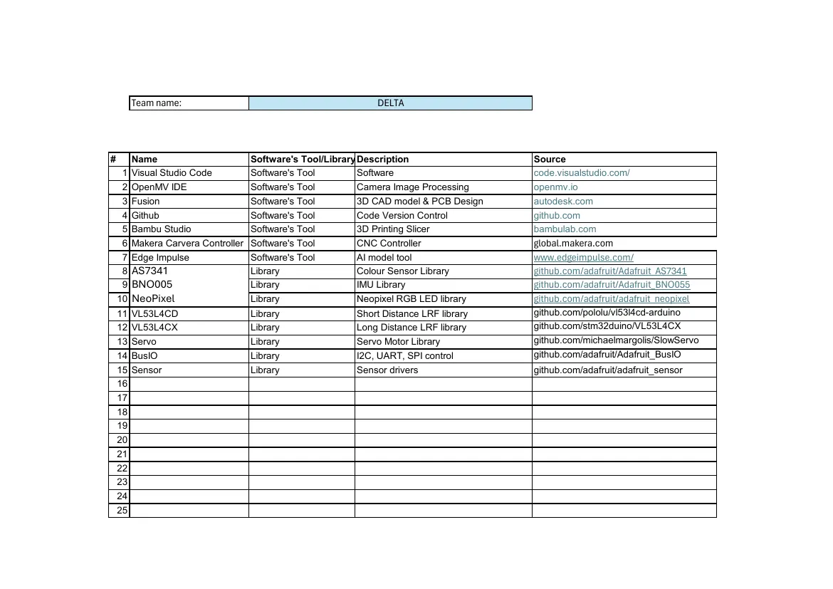
Read the text of this document — 739 words
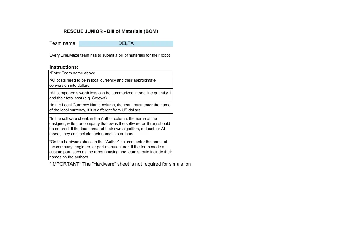
RESCUE JUNIOR - Bill of Materials (BOM)

Team name:                              DELTA

Every Line/Maze team has to submit a bill of materials for their robot

Instructions:
*Enter Team name above
*All costs need to be in local currency and their approximate
conversion into dollars.
*All components worth less can be summarized in one line quantity 1
and their total cost (e.g. Screws)
*In the Local Currency Name column, the team must enter the name
of the local currency, if it is different from US dollars.

*In the software sheet, in the Author column, the name of the
designer, writer, or company that owns the software or library should
be entered. If the team created their own algorithm, dataset, or AI
model, they can include their names as authors.
*On the hardware sheet, in the "Author" column, enter the name of
the company, engineer, or part manufacturer. If the team made a
custom part, such as the robot housing, the team should include their
names as the authors.
*IMPORTANT* The "Hardware" sheet is not required for simulation
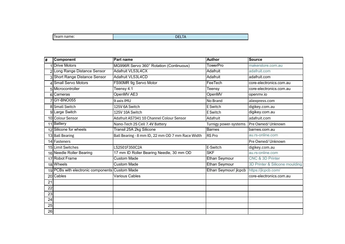
         Team name:                                                      DELTA

#      Component                       Part name                                          Author                  Source
     1 Drive Motors                    MG996R Servo 360° Rotation (Continuous)            TowerPro                makerstore.com.au
     2 Long Range Distance Sensor      Adafruit VL53L4CX                                  Adafruit                adafruit.com
     3 Short Range Distance Sensor     Adafruit VL53L4CD                                  Adafruit                adafruit.com
     4 Small Servo Motors              FS90MR 9g Servo Motor                              FeeTech                 core-electronics.com.au
     5 Microcontroller                 Teensy 4.1                                         Teensy                  core-electronics.com.au
     6 Cameras                         OpenMV AE3                                         OpenMV                  openmv.io
     7 GY-BNO055                       9 axis IMU                                         No Brand                aliexpress.com
     8 Small Switch                    125V 6A Switch                                     E Switch                digikey.com.au
     9 Large Switch                    125V 10A Switch                                    E Switch                digikey.com.au
    10 Colour Sensor                   Adafruit AS7341 10 Channel Colour Sensor           Adafruit                adafruit.com
    11 Battery                         Nano-Tech 2S Cell 7.4V Battery                     Turnigy power-systems   Pre Owned/ Unknown
    12 Silicone for wheels             Transil 25A 2kg Silicone                           Barnes                  barnes.com.au
    13 Ball Bearing                    Ball Bearing - 8 mm ID, 22 mm OD 7 mm Race Width   RS Pro                  au.rs-online.com
    14 Fasteners                                                                                                  Pre Owned/ Unknown
    15 Limit Switches                  LS2501F350C2A                                      E-Switch                digikey.com.au
    16 Needle  Roller Bearing          17 mm ID Roller Bearing Needle, 30 mm OD           SKF                     au.rs-online.com
    17 Robot Frame                     Custom Made                                        Ethan Seymour           CNC & 3D Printer
    18 Wheels                          Custom Made                                        Ethan Seymour           3D Printer & Silicone moulding
    19 PCBs with electronic components Custom Made                                        Ethan Seymour/ jlcpcb   https://jlcpcb.com/
    20 Cables                          Various Cables                                                             core-electronics.com.au
    21
    22
    23
    24
    25
    26
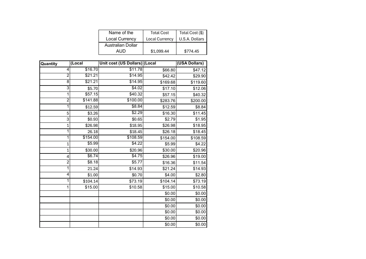
                              Name of the            Total Cost     Total Cost ($)
                             Local Currency        Local Currency   U.S.A. Dollars
                             Australian Dollar
                                  AUD                $1,099.44        $774.45
             Unit cost                            Total Cost      Total Cost
Quantity     (Local        Unit cost (US Dollars) (Local          (USA Dollars)
           4        $16.70                $11.78           $66.80         $47.12
           2        $21.21                $14.95           $42.42         $29.90
           8        $21.21                $14.95          $169.68        $119.60
           3         $5.70                 $4.02           $17.10         $12.06
           1        $57.15                $40.32           $57.15         $40.32
           2       $141.88               $100.00          $283.76        $200.00
           1        $12.59                 $8.84           $12.59          $8.84
           5         $3.26                 $2.29           $16.30         $11.45
           3         $0.93                 $0.65            $2.79           $1.95
           1        $26.98                $18.95           $26.98          $18.95
           1         26.18                $18.45           $26.18          $18.45
           1      $154.00               $108.59           $154.00         $108.59
           1        $5.99                 $4.22             $5.99           $4.22
           1        $30.00                $20.96           $30.00          $20.96
           4         $6.74                 $4.75           $26.96          $19.00
           2         $8.18                 $5.77           $16.36          $11.54
           1         21.24                $14.93           $21.24          $14.93
           4         $1.00                 $0.70            $4.00           $2.80
           1       $104.14                $73.19          $104.14          $73.19
           1        $15.00                $10.58           $15.00          $10.58
                                                            $0.00           $0.00
                                                            $0.00           $0.00
                                                            $0.00           $0.00
                                                            $0.00           $0.00
                                                            $0.00           $0.00
                                                            $0.00           $0.00
       Team name:                                            DELTA

#      Name                        Software's Tool/LibraryDescription                 Source
     1 Visual Studio Code          Software's Tool        Software                    code.visualstudio.com/
     2 OpenMV IDE                  Software's Tool        Camera Image Processing     openmv.io
     3 Fusion                      Software's Tool        3D CAD model & PCB Design   autodesk.com
     4 Github                      Software's Tool        Code Version Control        github.com
     5 Bambu Studio                Software's Tool        3D Printing Slicer          bambulab.com
     6 Makera Carvera Controller   Software's Tool        CNC Controller              global.makera.com
     7 Edge Impulse                Software's Tool        AI model tool               www.edgeimpulse.com/
     8 AS7341                      Library                Colour Sensor Library       github.com/adafruit/Adafruit_AS7341
     9 BNO005                      Library                IMU Library                 github.com/adafruit/Adafruit_BNO055
    10 NeoPixel                    Library                Neopixel RGB LED library    github.com/adafruit/adafruit_neopixel
    11 VL53L4CD                    Library              Short Distance LRF library    github.com/pololu/vl53l4cd-arduino
    12 VL53L4CX                    Library              Long Distance LRF library     github.com/stm32duino/VL53L4CX
    13 Servo                       Library              Servo Motor Library           github.com/michaelmargolis/SlowServo
    14 BusIO                       Library              I2C, UART, SPI control        github.com/adafruit/Adafruit_BusIO
    15 Sensor                      Library              Sensor drivers                github.com/adafruit/adafruit_sensor
    16
    17
    18
    19
    20
    21
    22
    23
    24
    25
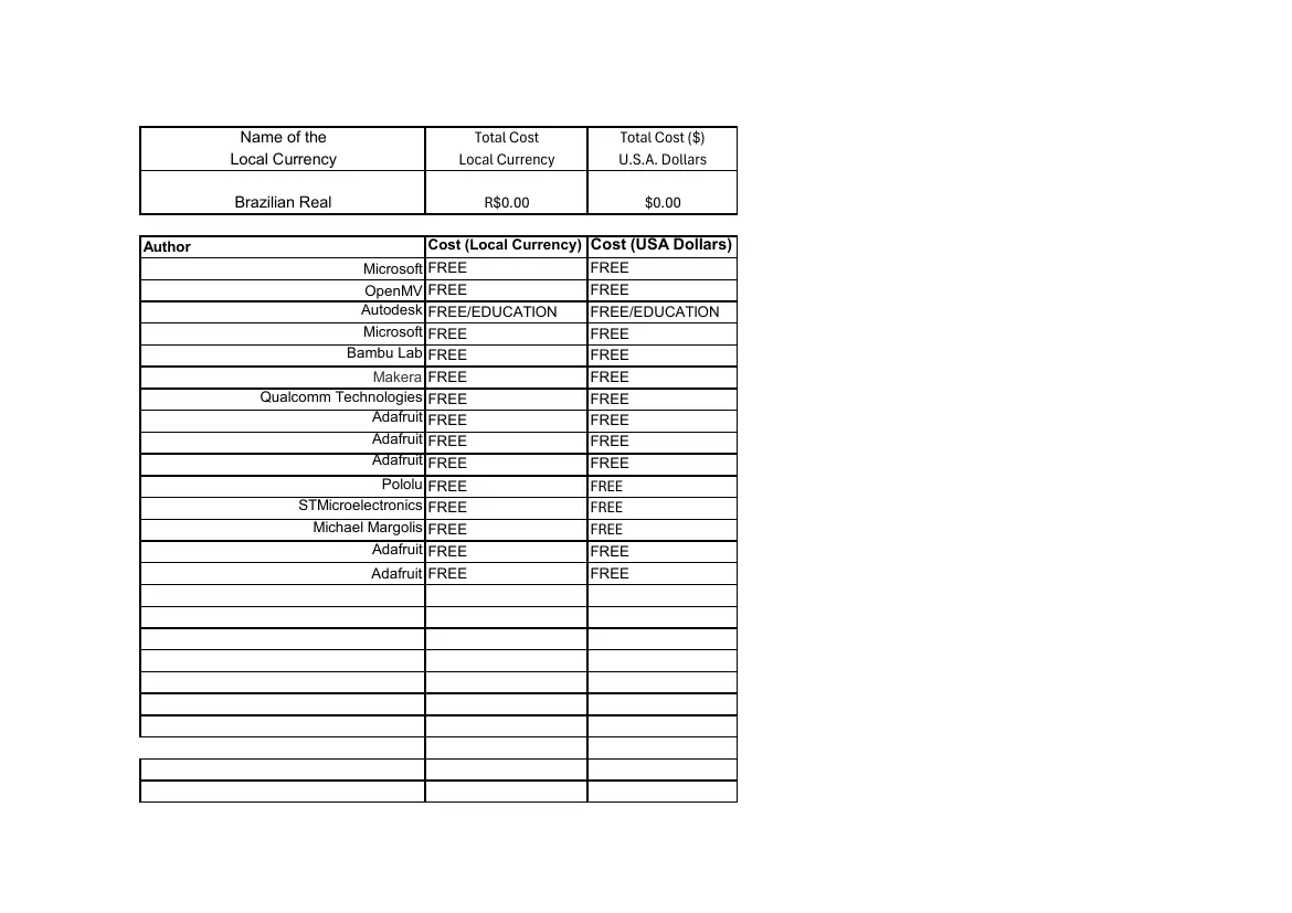
          Name of the                  Total Cost         Total Cost ($)
         Local Currency              Local Currency       U.S.A. Dollars

         Brazilian Real                   R$0.00              $0.00

Author                           Cost (Local Currency) Cost (USA Dollars)
                          Microsoft FREE              FREE
                          OpenMV FREE                 FREE
                         Autodesk FREE/EDUCATION      FREE/EDUCATION
                          Microsoft FREE              FREE
                       Bambu Lab FREE                 FREE
                           Makera FREE                FREE
            Qualcomm Technologies FREE                FREE
                           Adafruit FREE              FREE
                           Adafruit FREE              FREE
                           Adafruit FREE              FREE
                             Pololu FREE              FREE
                 STMicroelectronics FREE              FREE
                   Michael Margolis FREE              FREE
                           Adafruit FREE              FREE
                          Adafruit FREE               FREE

Open as plain text

5 pages, rendered as images so they load quickly. The text above is the document's own, extracted from the PDF.

Download the original PDF (202 KB) from GitHub

Source code

The team's own source code, 34 KB. It is a download rather than part of this page, because a zip is something you open on your computer. It comes from GitHub, which some school networks block.

Download Delta's source code