
System Override
Document register
- Poster1 pagePublished
- Presentation videoYouTubePublished
- Bill of materials70 KBPublished
- Team description paper10 pagesPublished
- Engineering journalNot shared
- Source code24 KB · GitHubPublished
Sharing each document is the team's decision. “Not shared” means this team chose not to publish it, or did not submit one — not that it is missing from the archive.
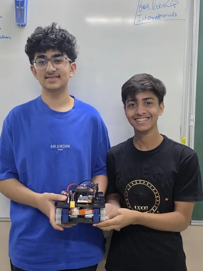
In their words
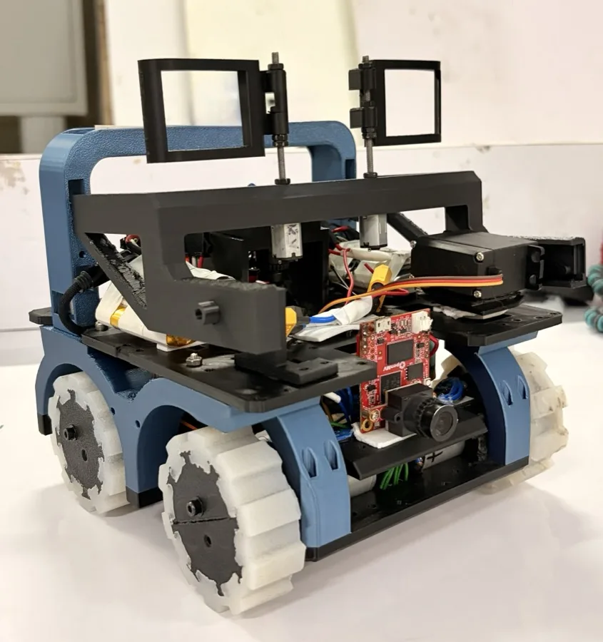
Our robot is a fully open-source, high-performance system designed for speed, precision, and adaptability, replacing educational robotics controllers with two OpenMV H7 Plus cameras for onboard vision processing and motor control, while a Raspberry Pi Pico 2 W acts as a secondary controller to handle additional sensor inputs and communicate commands to the camera. The main OpenMV performs line following while a second one handles evacuation tasks using a custom FOMO-based object detection model trained on over 4,000 manually labelled images with Edge Impulse, enabling fast and accurate victim identification. The Pico interfaces with an I2C multiplexer that controls two time-of-flight (TOF) sensors, each configured with region-of-interest (ROI) settings for precise and flexible distance sensing, along with a BNO055 gyro for ramp stability and accurate yaw-based navigation, and an RGB light sensor for detecting entry to the evacuation zone and goal tile. The robot uses two TB6612FNG motor drivers—one for a four-motor drivetrain and another for a dual
N20 motor claw for victim pickup, which also integrates a conductivity sensor system to detect live victims by completing an electrical circuit. Additionally, two servos are used for lifting the arm. The robot also features custom silicone wheels for better traction and grip. The robot is designed in Fusion 360 and manufactured through 3D printing.
Poster
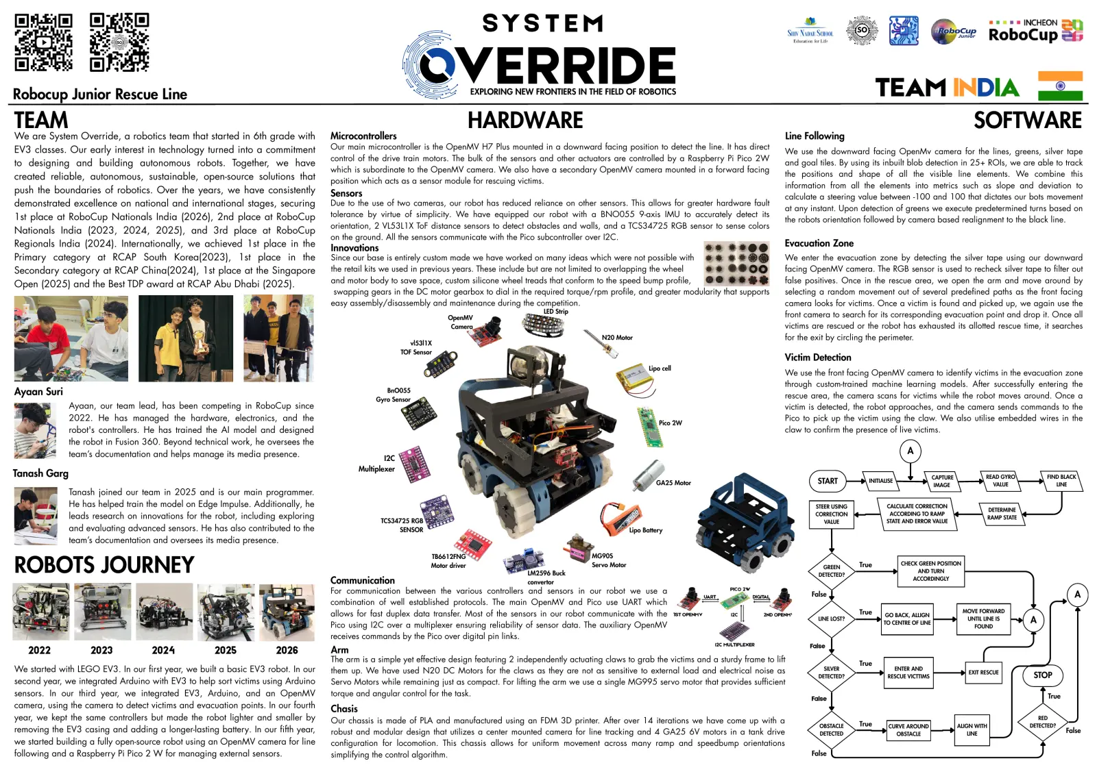
Read the text of this document — 1191 words
S Y S T E M
VERRIDE
SO
Robocup Junior Rescue Line EXPLORING NEW FRONTIERS IN THE FIELD OF ROBOTICS TEAM INDIA
TEAM HARDWARE SOFTWARE
We are System Override, a robotics team that started in 6th grade with Microcontrollers Line Following
EV3 classes. Our early interest in technology turned into a commitment Our main microcontroller is the OpenMV H7 Plus mounted in a downward facing position to detect the line. It has direct
We use the downward facing OpenMv camera for the lines, greens, silver tape
control of the drive train motors. The bulk of the sensors and other actuators are controlled by a Raspberry Pi Pico 2W
to designing and building autonomous robots. Together, we have and goal tiles. By using its inbuilt blob detection in 25+ ROIs, we are able to track
which is subordinate to the OpenMV camera. We also have a secondary OpenMV camera mounted in a forward facing
created reliable, autonomous, sustainable, open-source solutions that the positions and shape of all the visible line elements. We combine this
position which acts as a sensor module for rescuing victims.
information from all the elements into metrics such as slope and deviation to
push the boundaries of robotics. Over the years, we have consistently Sensors calculate a steering value between -100 and 100 that dictates our bots movement
demonstrated excellence on national and international stages, securing Due to the use of two cameras, our robot has reduced reliance on other sensors. This allows for greater hardware fault
at any instant. Upon detection of greens we execute predetermined turns based on
1st place at RoboCup Nationals India (2026), 2nd place at RoboCup tolerance by virtue of simplicity. We have equipped our robot with a BNO055 9-axis IMU to accurately detect its
the robots orientation followed by camera based realignment to the black line.
orientation, 2 VL53L1X ToF distance sensors to detect obstacles and walls, and a TCS34725 RGB sensor to sense colors
Nationals India (2023, 2024, 2025), and 3rd place at RoboCup
on the ground. All the sensors communicate with the Pico subcontroller over I2C.
Regionals India (2024). Internationally, we achieved 1st place in the Evacuation Zone
Innovations
Primary category at RCAP South Korea(2023), 1st place in the Since our base is entirely custom made we have worked on many ideas which were not possible with We enter the evacuation zone by detecting the silver tape using our downward
Secondary category at RCAP China(2024), 1st place at the Singapore the retail kits we used in previous years. These include but are not limited to overlapping the wheel facing OpenMV camera. The RGB sensor is used to recheck silver tape to filter out
and motor body to save space, custom silicone wheel treads that conform to the speed bump profile, false positives. Once in the rescue area, we open the arm and move around by
Open (2025) and the Best TDP award at RCAP Abu Dhabi (2025).
swapping gears in the DC motor gearbox to dial in the required torque/rpm profile, and greater modularity that supports selecting a random movement out of several predefined paths as the front facing
easy assembly/disassembly and maintenance during the competition. camera looks for victims. Once a victim is found and picked up, we again use the
LED Strip
OpenMV front camera to search for its corresponding evacuation point and drop it. Once all
Camera victims are rescued or the robot has exhausted its allotted rescue time, it searches
N20 Motor for the exit by circling the perimeter.
vl53l1X
TOF Sensor
Victim Detection
Lipo cell
We use the front facing OpenMV camera to identify victims in the evacuation zone
through custom-trained machine learning models. After successfully entering the
Ayaan Suri BnO055
rescue area, the camera scans for victims while the robot moves around. Once a
Gyro Sensor
Ayaan, our team lead, has been competing in RoboCup since victim is detected, the robot approaches, and the camera sends commands to the
2022. He has managed the hardware, electronics, and the Pico to pick up the victim using the claw. We also utilise embedded wires in the
Pico 2W
robot's controllers. He has trained the AI model and designed claw to confirm the presence of live victims.
the robot in Fusion 360. Beyond technical work, he oversees the
team’s documentation and helps manage its media presence. A
I2C
Multiplexer
Tanash Garg CAPTURE READ GYRO FIND BLACK
GA25 Motor START INITIALISE
IMAGE VALUE LINE
Tanash joined our team in 2025 and is our main programmer.
He has helped train the model on Edge Impulse. Additionally, he STEER USING CALCULATE CORRECTION
DETERMINE
CORRECTION ACCORDING TO RAMP
leads research on innovations for the robot, including exploring TCS34725 RGB STATE AND ERROR VALUE
RAMP STATE
VALUE
and evaluating advanced sensors. He has also contributed to the SENSOR Lipo Battery
team’s documentation and oversees its media presence.
TB6612FNG MG90S
ROBOTS JOURNEY Communication
Motor driver
LM2596 Buck
Servo Motor GREEN
DETECTED?
True CHECK GREEN POSITION
AND TURN
ACCORDINGLY
convertor
For communication between the various controllers and sensors in our robot we use a False A
combination of well established protocols. The main OpenMV and Pico use UART which
allows for fast duplex data transfer. Most of the sensors in our robot communicate with the True GO BACK, ALLIGN
MOVE FORWARD
LINE LOST?
TO CENTRE OF LINE
UNTIL LINE IS A
Pico using I2C over a multiplexer ensuring reliability of sensor data. The auxiliary OpenMV FOUND
receives commands by the Pico over digital pin links.
False
2022 2023 2024 2025 2026 Arm
The arm is a simple yet effective design featuring 2 independently actuating claws to grab the victims and a sturdy frame to lift True
We started with LEGO EV3. In our first year, we built a basic EV3 robot. In our them up. We have used N20 DC Motors for the claws as they are not as sensitive to external load and electrical noise as SILVER ENTER AND
EXIT RESCUE
DETECTED? RESCUE VICTTIMS STOP
second year, we integrated Arduino with EV3 to help sort victims using Arduino Servo Motors while remaining just as compact. For lifting the arm we use a single MG995 servo motor that provides sufficient
sensors. In our third year, we integrated EV3, Arduino, and an OpenMV torque and angular control for the task. True
False
camera, using the camera to detect victims and evacuation points. In our fourth Chasis
year, we kept the same controllers but made the robot lighter and smaller by Our chassis is made of PLA and manufactured using an FDM 3D printer. After over 14 iterations we have come up with a RED
OBSTACLE True CURVE AROUND ALIGN WITH DETECTED?
removing the EV3 casing and adding a longer-lasting battery. In our fifth year, robust and modular design that utilizes a center mounted camera for line tracking and 4 GA25 6V motors in a tank drive DETECTED OBSTACLE LINE
False
we started building a fully open-source robot using an OpenMV camera for line configuration for locomotion. This chassis allows for uniform movement across many ramp and speedbump orientations
following and a Raspberry Pi Pico 2 W for managing external sensors. simplifying the control algorithm. False
1 page, rendered as images so they load quickly. The text above is the document's own, extracted from the PDF.
Presentation video
Hosted on YouTube. The player loads only when you press play.
Bill of materials
Shown as the original PDF, because this one is smaller that way and its text stays selectable and searchable.
Team description paper
Show the remaining 7 pages
Read the text of this document — 4657 words
RoboCupJunior Rescue Line 2026
Team Description Paper
System Override
Abstract
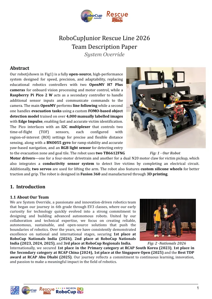
Our robot(shown in Fig1) is a fully open-source, high-performance
system designed for speed, precision, and adaptability, replacing
educational robotics controllers with two OpenMV H7 Plus
cameras for onboard vision processing and motor control, while a
Raspberry Pi Pico 2 W acts as a secondary controller to handle
additional sensor inputs and communicate commands to the
camera. The main OpenMV performs line following while a second
one handles evacuation tasks using a custom FOMO-based object
detection model trained on over 4,000 manually labelled images
with Edge Impulse, enabling fast and accurate victim identification.
The Pico interfaces with an I2C multiplexer that controls two
time-of-flight (TOF) sensors, each configured with
region-of-interest (ROI) settings for precise and flexible distance
sensing, along with a BNO055 gyro for ramp stability and accurate
yaw-based navigation, and an RGB light sensor for detecting entry
to the evacuation zone and goal tile. The robot uses two TB6612FNG Fig: 1 - Our Robot
Motor drivers—one for a four-motor drivetrain and another for a dual N20 motor claw for victim pickup, which
also integrates a conductivity sensor system to detect live victims by completing an electrical circuit.
Additionally, two servos are used for lifting the arm. The robot also features custom silicone wheels for better
traction and grip. The robot is designed in Fusion 360 and manufactured through 3D printing.
1. Introduction
1.1 About Our Team
We are System Override, a passionate and innovation-driven robotics team
that began our journey in 6th grade through EV3 classes, where our early
curiosity for technology quickly evolved into a strong commitment to
designing and building advanced autonomous robots. United by our
collaboration and technical expertise, we focus on creating reliable,
autonomous, sustainable, and open-source solutions that push the
boundaries of robotics. Over the years, we have consistently demonstrated
excellence on national and international stages, securing 1st place at
RoboCup Nationals India (2026), 2nd place at RoboCup Nationals
India (2023, 2024, 2025), and 3rd place at RoboCup Regionals India. Fig: 2 -Nationals 2026
Internationally, we secured 1st place in the Primary category at RCAP South Korea (2023), 1st place in
the Secondary category at RCAP China (2024), 1st place at the Singapore Open (2025) and the Best TDP
award at RCAP Abu Dhabi (2025). Our journey reflects a commitment to continuous learning, innovation,
and passion to make a meaningful impact in the field of robotics.
1
1.2 Team Members
Our team has two members:
Ayaan Suri: Ayaan, our team lead, has been competing in RoboCup since 2022 and plays a key role in the
robot’s hardware and electrical systems. He has also trained the AI model using Edge Impulse and captured
image data for model development. Additionally, he has used CAD Designing for all 3D-printed components in
Autodesk Fusion 360. Beyond technical work, he oversees the team’s documentation and helps manage its
media presence.
Tanash Garg: Tanash has been competing in RoboCup since 2025 and plays a key role in managing the team’s
software. He is the main programmer of our team. He has also helped train the model on Edge Impulse.
Additionally, he leads research on innovations for the robot, including exploring and evaluating advanced
sensors. He is extensively involved in procuring various components for our Robot.
2. Project Planning
2.1 Overall Project Plan
2.1.1 Team Objective
The primary objective of our team is to design and develop a fully autonomous robot capable of completing
the RoboCup Junior Rescue Line challenge with consistent reliability, efficiency, and accuracy. To accomplish
this objective, the system is engineered to meet the following requirements:
● Mechanical Design: Develop a compact, competition-compliant robot capable of integrating all required
sensors, controllers, and rescue mechanisms.
● Electrical Integration: Ensure stable power distribution, reliable wiring, and efficient communication
between all microcontrollers and sensors.
● Hardware Performance: Implement accurate sensing systems for line following, object detection, vision
sensing, obstacles and Ramps.
● Software and Logic Development: Create reliable algorithms for autonomous navigation, object
detection, victim rescue, and real-time decision-making.
● Testing: Create test cases based on different scenarios to minimise errors and to achieve design goals.
● Resource Optimisation: Design within the limits of available materials, budget, and battery capacity while
ensuring it's a compact robot.
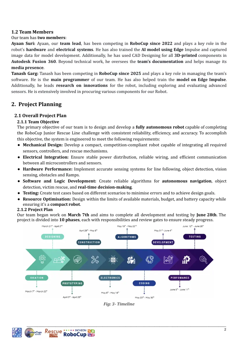
2.1.2 Project Plan
Our team began work on March 7th and aims to complete all development and testing by June 28th. The
project is divided into 10 phases, each with responsibilities and review gates to ensure steady progress.
Fig: 3- Timeline
_______________________________________________________________________________________________________________
2
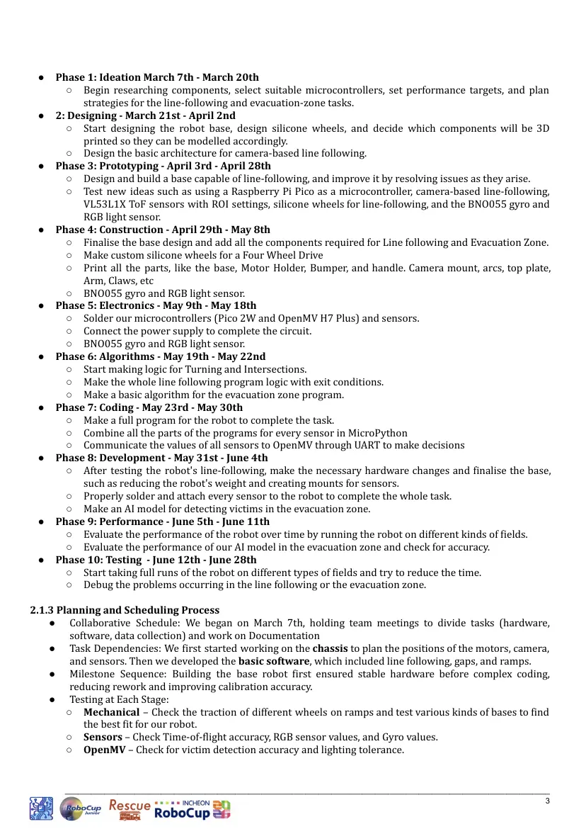
● Phase 1: Ideation March 7th - March 20th
○ Begin researching components, select suitable microcontrollers, set performance targets, and plan
strategies for the line-following and evacuation-zone tasks.
● 2: Designing - March 21st - April 2nd
○ Start designing the robot base, design silicone wheels, and decide which components will be 3D
printed so they can be modelled accordingly.
○ Design the basic architecture for camera-based line following.
● Phase 3: Prototyping - April 3rd - April 28th
○ Design and build a base capable of line-following, and improve it by resolving issues as they arise.
○ Test new ideas such as using a Raspberry Pi Pico as a microcontroller, camera-based line-following,
VL53L1X ToF sensors with ROI settings, silicone wheels for line-following, and the BNO055 gyro and
RGB light sensor.
● Phase 4: Construction - April 29th - May 8th
○ Finalise the base design and add all the components required for Line following and Evacuation Zone.
○ Make custom silicone wheels for a Four Wheel Drive
○ Print all the parts, like the base, Motor Holder, Bumper, and handle. Camera mount, arcs, top plate,
Arm, Claws, etc
○ BNO055 gyro and RGB light sensor.
● Phase 5: Electronics - May 9th - May 18th
○ Solder our microcontrollers (Pico 2W and OpenMV H7 Plus) and sensors.
○ Connect the power supply to complete the circuit.
○ BNO055 gyro and RGB light sensor.
● Phase 6: Algorithms - May 19th - May 22nd
○ Start making logic for Turning and Intersections.
○ Make the whole line following program logic with exit conditions.
○ Make a basic algorithm for the evacuation zone program.
● Phase 7: Coding - May 23rd - May 30th
○ Make a full program for the robot to complete the task.
○ Combine all the parts of the programs for every sensor in MicroPython
○ Communicate the values of all sensors to OpenMV through UART to make decisions
● Phase 8: Development - May 31st - June 4th
○ After testing the robot's line-following, make the necessary hardware changes and finalise the base,
such as reducing the robot's weight and creating mounts for sensors.
○ Properly solder and attach every sensor to the robot to complete the whole task.
○ Make an AI model for detecting victims in the evacuation zone.
● Phase 9: Performance - June 5th - June 11th
○ Evaluate the performance of the robot over time by running the robot on different kinds of fields.
○ Evaluate the performance of our AI model in the evacuation zone and check for accuracy.
● Phase 10: Testing - June 12th - June 28th
○ Start taking full runs of the robot on different types of fields and try to reduce the time.
○ Debug the problems occurring in the line following or the evacuation zone.
2.1.3 Planning and Scheduling Process
● Collaborative Schedule: We began on March 7th, holding team meetings to divide tasks (hardware,
software, data collection) and work on Documentation
● Task Dependencies: We first started working on the chassis to plan the positions of the motors, camera,
and sensors. Then we developed the basic software, which included line following, gaps, and ramps.
● Milestone Sequence: Building the base robot first ensured stable hardware before complex coding,
reducing rework and improving calibration accuracy.
● Testing at Each Stage:
○ Mechanical – Check the traction of different wheels on ramps and test various kinds of bases to find
the best fit for our robot.
○ Sensors – Check Time-of-flight accuracy, RGB sensor values, and Gyro values.
○ OpenMV – Check for victim detection accuracy and lighting tolerance.
_______________________________________________________________________________________________________________
3
○ System integration – Test full rescue line runs with an evacuation zone to validate the performance
of the robot.
● Adjustments: After each phase, we reviewed the results, fixed hardware and software issues, and
reallocated time to stay on track for 28th June.
2.2 Integration Plan
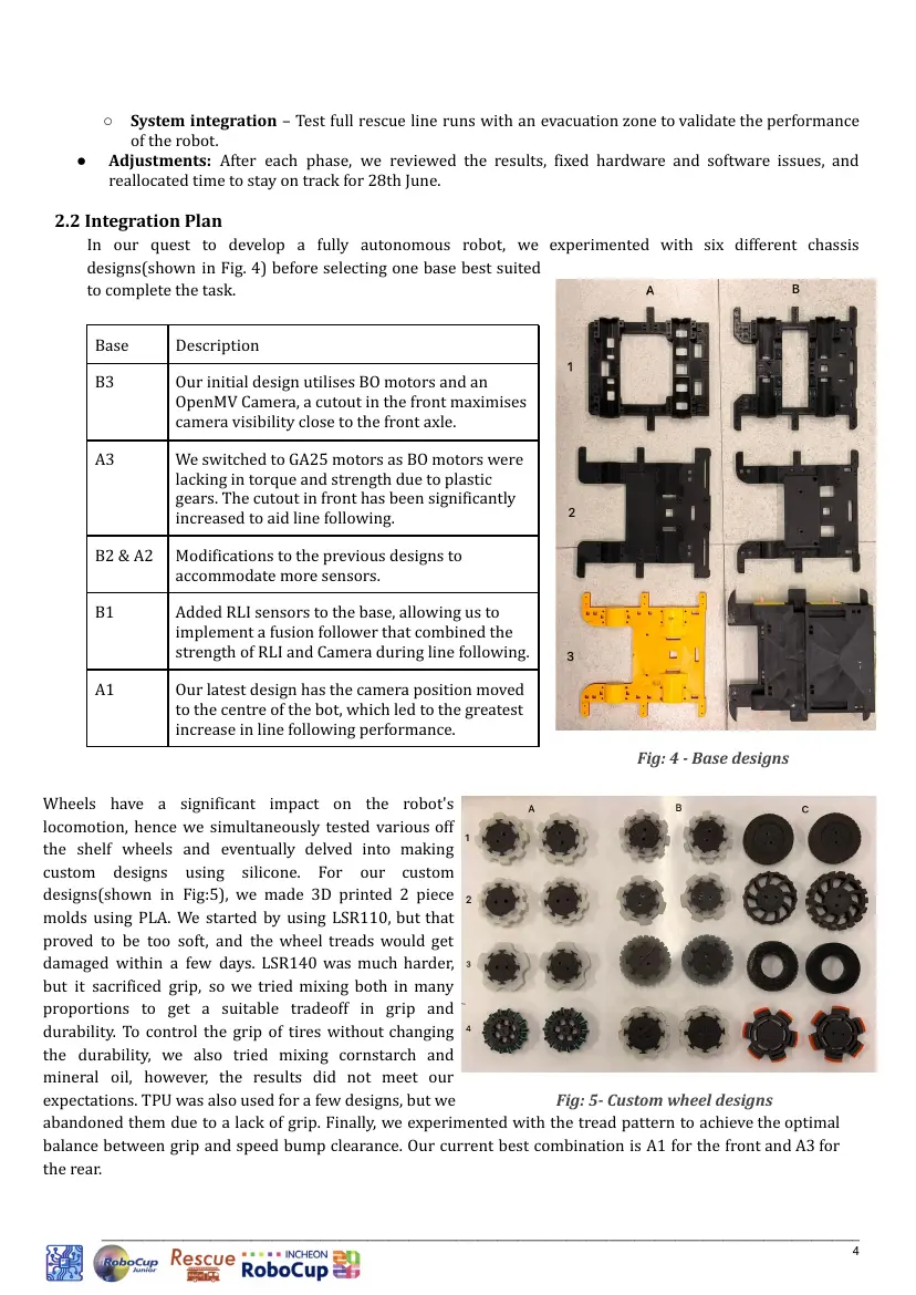
In our quest to develop a fully autonomous robot, we experimented with six different chassis
designs(shown in Fig. 4) before selecting one base best suited
to complete the task.
Base Description
B3 Our initial design utilises BO motors and an
OpenMV Camera, a cutout in the front maximises
camera visibility close to the front axle.
A3 We switched to GA25 motors as BO motors were
lacking in torque and strength due to plastic
gears. The cutout in front has been significantly
increased to aid line following.
B2 & A2 Modifications to the previous designs to
accommodate more sensors.
B1 Added RLI sensors to the base, allowing us to
implement a fusion follower that combined the
strength of RLI and Camera during line following.
A1 Our latest design has the camera position moved
to the centre of the bot, which led to the greatest
increase in line following performance.
Fig: 4 - Base designs
Wheels have a significant impact on the robot's
locomotion, hence we simultaneously tested various off
the shelf wheels and eventually delved into making
custom designs using silicone. For our custom
designs(shown in Fig:5), we made 3D printed 2 piece
molds using PLA. We started by using LSR110, but that
proved to be too soft, and the wheel treads would get
damaged within a few days. LSR140 was much harder,
but it sacrificed grip, so we tried mixing both in many
proportions to get a suitable tradeoff in grip and
durability. To control the grip of tires without changing
the durability, we also tried mixing cornstarch and
mineral oil, however, the results did not meet our
expectations. TPU was also used for a few designs, but we Fig: 5- Custom wheel designs
abandoned them due to a lack of grip. Finally, we experimented with the tread pattern to achieve the optimal
balance between grip and speed bump clearance. Our current best combination is A1 for the front and A3 for
the rear.
_______________________________________________________________________________________________________________
4
In previous competitions, we have used RLI and RGB sensors with the LEGO EV3 platform. Since we are
familiar with such sensors, we tried the same in our open source bot. Although the results were not terrible,
we instead opted to use a camera for line following. Despite the camera’s sensitivity to environmental lighting,
it offers major advantages over RLI sensors. Firstly, it is not sensitive to ground height as compared to RLI
sensors, whose values vary wildly when the robot’s distance from the ground changes as a result of running
over speed bumps and ramp peaks. Secondly, it captures a much wider area to draw information from. While
an RLI sensor is akin to one pixel of information, a low-res camera still has over 70k pixels worth of
information. This allows us to not lose the line in varying scenarios, which is necessary to complete the task
effectively.
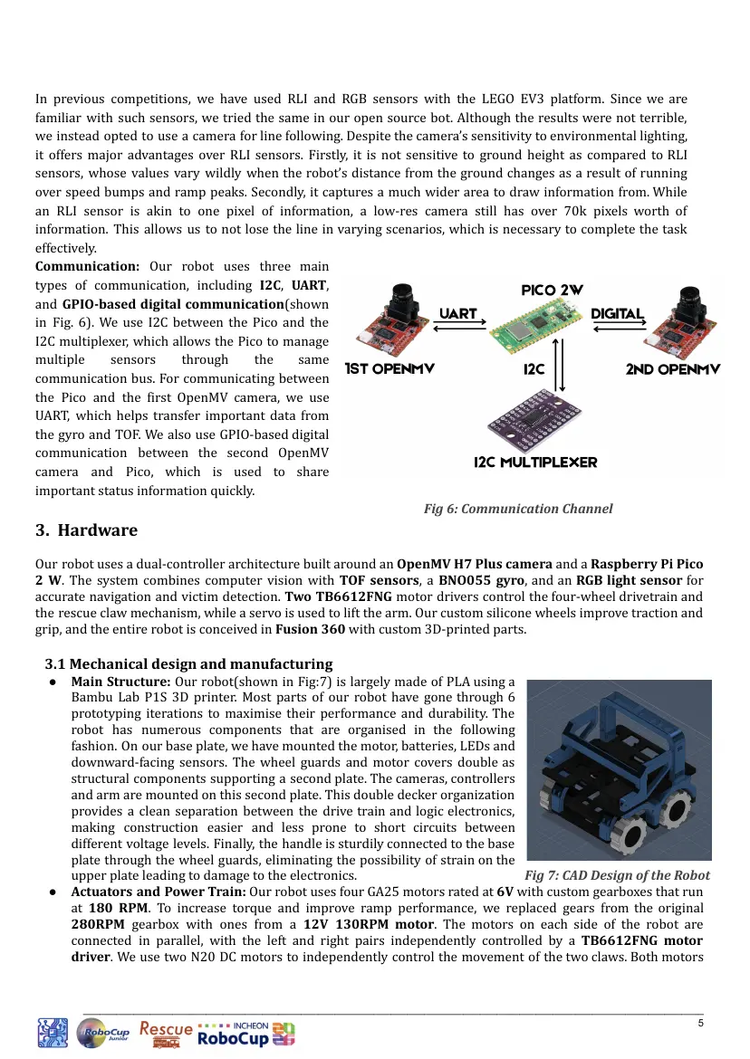
Communication: Our robot uses three main
types of communication, including I2C, UART,
and GPIO-based digital communication(shown
in Fig. 6). We use I2C between the Pico and the
I2C multiplexer, which allows the Pico to manage
multiple sensors through the same
communication bus. For communicating between
the Pico and the first OpenMV camera, we use
UART, which helps transfer important data from
the gyro and TOF. We also use GPIO-based digital
communication between the second OpenMV
camera and Pico, which is used to share
important status information quickly.
Fig 6: Communication Channel
3. Hardware
Our robot uses a dual-controller architecture built around an OpenMV H7 Plus camera and a Raspberry Pi Pico
2 W. The system combines computer vision with TOF sensors, a BNO055 gyro, and an RGB light sensor for
accurate navigation and victim detection. Two TB6612FNG motor drivers control the four-wheel drivetrain and
the rescue claw mechanism, while a servo is used to lift the arm. Our custom silicone wheels improve traction and
grip, and the entire robot is conceived in Fusion 360 with custom 3D-printed parts.
3.1 Mechanical design and manufacturing
● Main Structure: Our robot(shown in Fig:7) is largely made of PLA using a
Bambu Lab P1S 3D printer. Most parts of our robot have gone through 6
prototyping iterations to maximise their performance and durability. The
robot has numerous components that are organised in the following
fashion. On our base plate, we have mounted the motor, batteries, LEDs and
downward-facing sensors. The wheel guards and motor covers double as
structural components supporting a second plate. The cameras, controllers
and arm are mounted on this second plate. This double decker organization
provides a clean separation between the drive train and logic electronics,
making construction easier and less prone to short circuits between
different voltage levels. Finally, the handle is sturdily connected to the base
plate through the wheel guards, eliminating the possibility of strain on the
upper plate leading to damage to the electronics. Fig 7: CAD Design of the Robot
● Actuators and Power Train: Our robot uses four GA25 motors rated at 6V with custom gearboxes that run
at 180 RPM. To increase torque and improve ramp performance, we replaced gears from the original
280RPM gearbox with ones from a 12V 130RPM motor. The motors on each side of the robot are
connected in parallel, with the left and right pairs independently controlled by a TB6612FNG motor
driver. We use two N20 DC motors to independently control the movement of the two claws. Both motors
_______________________________________________________________________________________________________________
5
are driven by a TB6612FNG motor driver, allowing reliable operation during victim pickup. We also use one
MG995 servo to lift the arm.
● Modules: Modularity is one of the key considerations we had in mind when designing our robot. Since the
robot assembles/disassembles using many modular subparts through a systematic procedure, carrying out
maintenance during the competition is highly efficient. Silicone wheels may wear out regularly; hence, we
have made them easily detachable. We have also designed the hubs as keyed fittings so there is no
possibility of misalignment during installation. The batteries are attached in a tray-like structure so that it
is easier to swap on the fly. Additionally, we have tried to keep the overall design composed of many
interlocking parts instead of large single pieces, making swaps in case of accidental damage that much
easier and also reducing print times during development.
● Rescue Mechanism: To rescue the victims in the rescue area and safely carry them to their respective
evacuation points, we have equipped our robot with an arm. To hold the victims during transport, our arm
has two independently actuated claws. The claws conform to the victim's shape such that the risk of them
slipping out once grabbed is reduced. Each claw is attached to a 6V N20 DC motor. We opted to use DC
motors since they are less likely to break under large external loads if the robot crashes into a wall while
searching for victims. Two MG90S Metal Gear Micro Servos work in tandem to lift the arm once a victim has
been securely grabbed by the claws. Once the robot has picked a victim and reached the corresponding
evacuation point, we lower the arm onto the evacuation point wall and gently release the victim. Instead of
sorting the victims after picking them up, we opted to pick them up in the required order in the first place,
thus reducing the need for complex rescue mechanism development and allowing us to prioritise testing
and improving reliability.
3.2 Electronic Design and Manufacturing
● Sensors used: The bulk of the input for the robot is obtained through the pair of OpenMV cameras. While
the forward-facing camera acts as a vision sensor for rescue related tasks like victim and evacuation point
detection, the downward-facing camera is responsible for line tracking and overall program control. Due to
the large amount of visual information our robot captures, it has reduced reliance on other sensors. This
allows for greater hardware fault tolerance by virtue of simplicity. To accurately detect the robot's
orientation on ramps, we have equipped it with a BNO055 9-axis IMU. This allows our robot to adjust its
line-following behaviour based on orientation and prevents slipping and falling off ramps. Since the robot is
compact, it is difficult to isolate the IMU from the magnetic flux generated by the DC motors, hence, we
ignore the magnetometer in our measurements. Two VL53L1X ToF distance sensors are used to detect
obstacles during line following and walls in the rescue area. Lastly, a TCS34725 RGB sensor is used to
sense colours on the ground. This is added as a double check for the
silver tape and goal tile, since relying on a single sensor may not be
enough, especially since the camera can be sensitive to environmental
lighting. All the sensors communicate with the Pico subcontroller over
I2C using a multiplexer. The Pico then parses the sensor data and
exposes it to the main OpenMV controller.
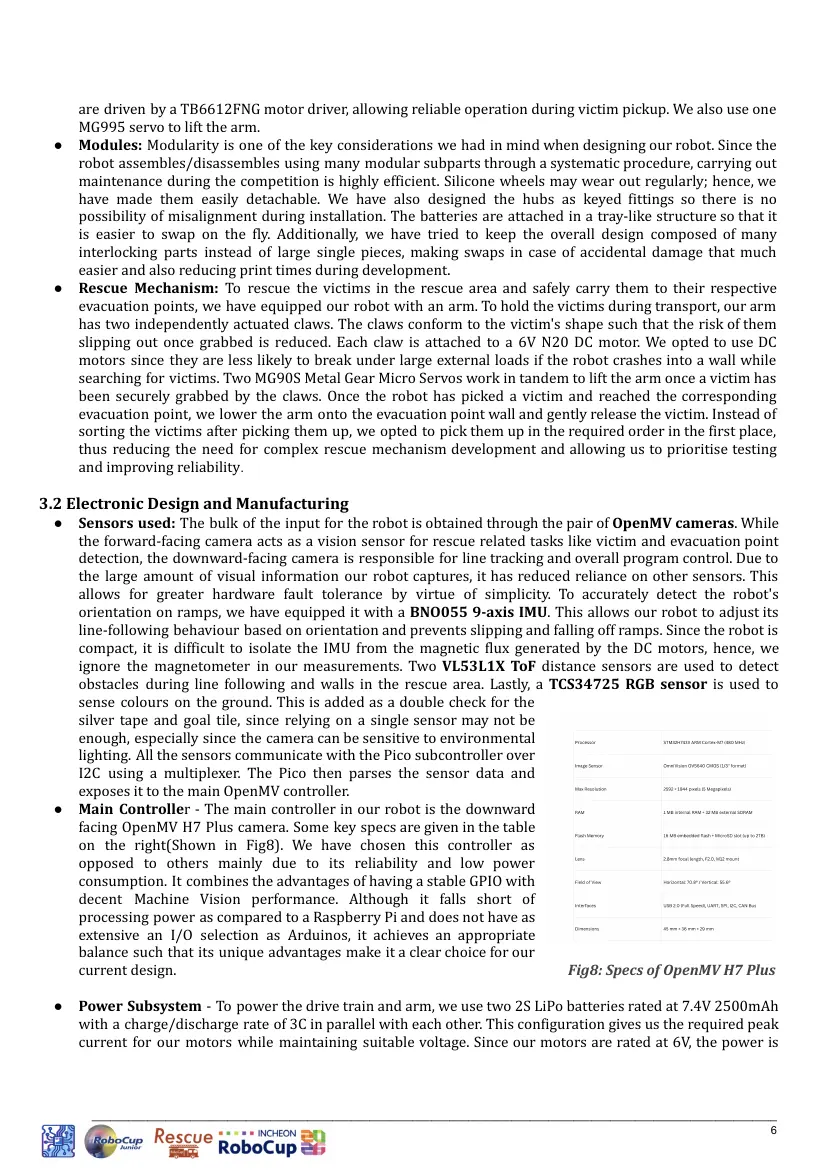
● Main Controller - The main controller in our robot is the downward
facing OpenMV H7 Plus camera. Some key specs are given in the table
on the right(Shown in Fig8). We have chosen this controller as
opposed to others mainly due to its reliability and low power
consumption. It combines the advantages of having a stable GPIO with
decent Machine Vision performance. Although it falls short of
processing power as compared to a Raspberry Pi and does not have as
extensive an I/O selection as Arduinos, it achieves an appropriate
balance such that its unique advantages make it a clear choice for our
current design. Fig8: Specs of OpenMV H7 Plus
● Power Subsystem - To power the drive train and arm, we use two 2S LiPo batteries rated at 7.4V 2500mAh
with a charge/discharge rate of 3C in parallel with each other. This configuration gives us the required peak
current for our motors while maintaining suitable voltage. Since our motors are rated at 6V, the power is
_______________________________________________________________________________________________________________
6
regulated to 6.25V using an LM2596 switch-mode buck converter. As a safety mechanism, we have added a
toggle switch in series with the battery, and an off-the-shelf battery level display is used in parallel.
To power the three controllers and all the sensors and LEDs in our robot, we make use of two 2500mAh
single-cell LiPo batteries equipped with a Seeed Studio BMS board.
● Actuator Control - Our robot has 6 DC motors in all, 4 for the drivetrain and 2 for the claws. These are
controlled by a pair of TB6612FNG H-bridge motor drivers. Input signals to the drivetrain controller are
provided by the main OpenMV camera over 6 digital lines that allow full directional and duty cycle control.
The claw motor driver is connected to the Pico through its digital pins. The MG995 servo motor has an
inbuilt controller and just needs to be provided with a 500us to 2500us HIGH pulse every 20ms to set its
target angle, which we achieve by using a PWM pin on the Pico.
4. Software
Since our robot has three controllers, it has three corresponding scripts running concurrently. The main control
loop runs on the downward facing OpenMV camera. The entire logic for line following, including obstacle
avoidance, ramp detection, goal tile stopping, and the rescue protocol, is included. The script on the Pico handles
polling of sensor values and controlling the arm as per the main controller's command. The front-facing OpenMV
detects victims and evacuation points in the rescue area using FOMO object detection models and blob detection
based on the main controller commands, with the Pico acting as the communication bridge between the two
cameras.
4.1 General Software Architecture
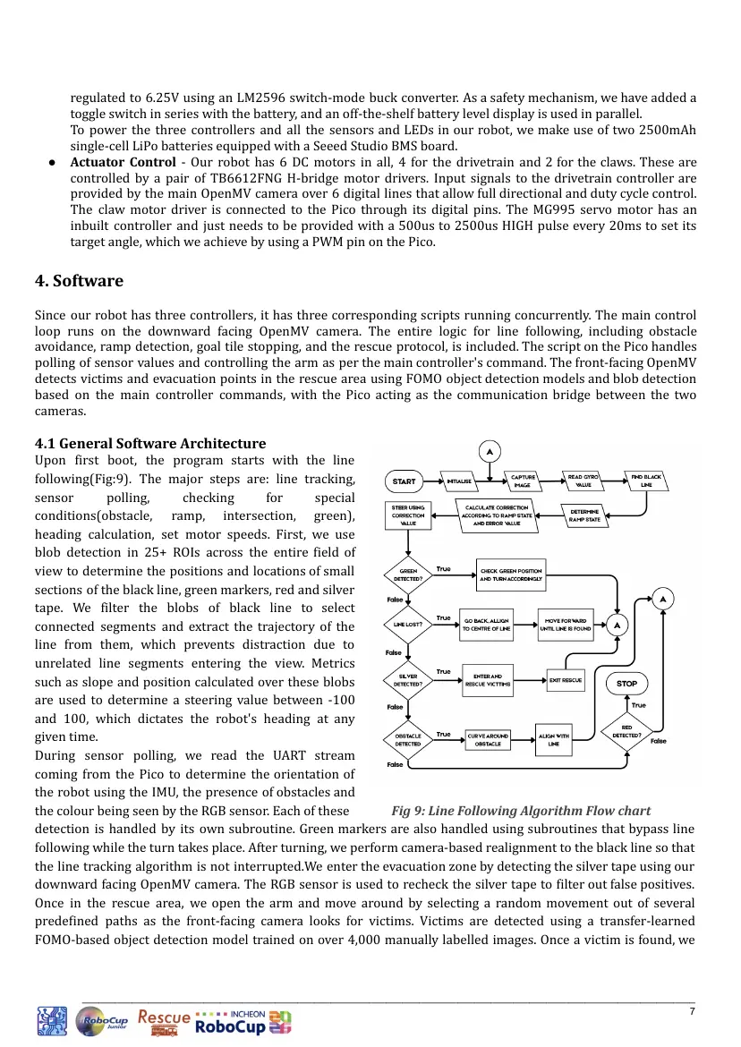
Upon first boot, the program starts with the line
following(Fig:9). The major steps are: line tracking,
sensor polling, checking for special
conditions(obstacle, ramp, intersection, green),
heading calculation, set motor speeds. First, we use
blob detection in 25+ ROIs across the entire field of
view to determine the positions and locations of small
sections of the black line, green markers, red and silver
tape. We filter the blobs of black line to select
connected segments and extract the trajectory of the
line from them, which prevents distraction due to
unrelated line segments entering the view. Metrics
such as slope and position calculated over these blobs
are used to determine a steering value between -100
and 100, which dictates the robot's heading at any
given time.
During sensor polling, we read the UART stream
coming from the Pico to determine the orientation of
the robot using the IMU, the presence of obstacles and
the colour being seen by the RGB sensor. Each of these Fig 9: Line Following Algorithm Flow chart
detection is handled by its own subroutine. Green markers are also handled using subroutines that bypass line
following while the turn takes place. After turning, we perform camera-based realignment to the black line so that
the line tracking algorithm is not interrupted.We enter the evacuation zone by detecting the silver tape using our
downward facing OpenMV camera. The RGB sensor is used to recheck the silver tape to filter out false positives.
Once in the rescue area, we open the arm and move around by selecting a random movement out of several
predefined paths as the front-facing camera looks for victims. Victims are detected using a transfer-learned
FOMO-based object detection model trained on over 4,000 manually labelled images. Once a victim is found, we
_______________________________________________________________________________________________________________
7
approach it in a straight line until we are in close proximity to it. Picked up, we again use the front camera to
search for its corresponding evacuation point and drop it. Once all victims are rescued or the robot has exhausted
its allotted rescue time, it searches for the exit by circling the perimeter.
4.2 Innovative Solutions
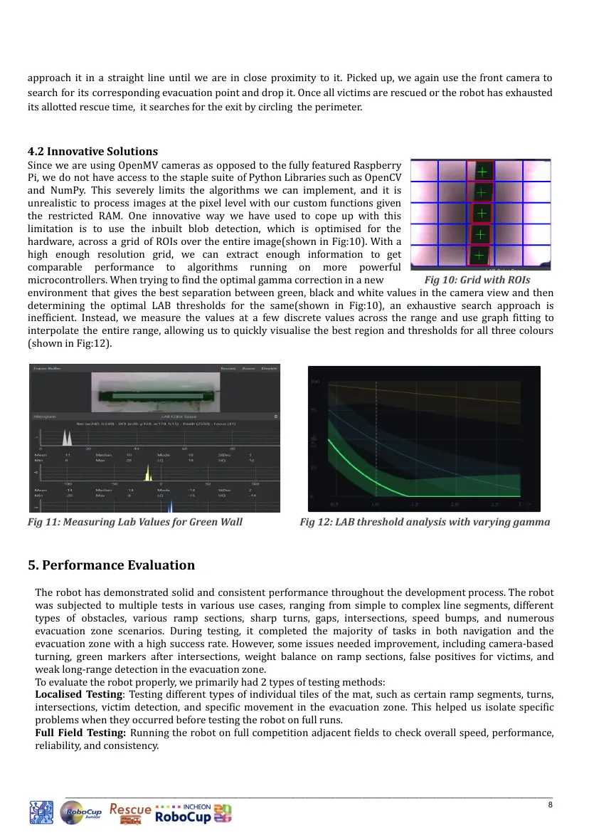
Since we are using OpenMV cameras as opposed to the fully featured Raspberry
Pi, we do not have access to the staple suite of Python Libraries such as OpenCV
and NumPy. This severely limits the algorithms we can implement, and it is
unrealistic to process images at the pixel level with our custom functions given
the restricted RAM. One innovative way we have used to cope up with this
limitation is to use the inbuilt blob detection, which is optimised for the
hardware, across a grid of ROIs over the entire image(shown in Fig:10). With a
high enough resolution grid, we can extract enough information to get
comparable performance to algorithms running on more powerful
microcontrollers. When trying to find the optimal gamma correction in a new Fig 10: Grid with ROIs
environment that gives the best separation between green, black and white values in the camera view and then
determining the optimal LAB thresholds for the same(shown in Fig:10), an exhaustive search approach is
inefficient. Instead, we measure the values at a few discrete values across the range and use graph fitting to
interpolate the entire range, allowing us to quickly visualise the best region and thresholds for all three colours
(shown in Fig:12).
Fig 11: Measuring Lab Values for Green Wall Fig 12: LAB threshold analysis with varying gamma
5. Performance Evaluation
The robot has demonstrated solid and consistent performance throughout the development process. The robot
was subjected to multiple tests in various use cases, ranging from simple to complex line segments, different
types of obstacles, various ramp sections, sharp turns, gaps, intersections, speed bumps, and numerous
evacuation zone scenarios. During testing, it completed the majority of tasks in both navigation and the
evacuation zone with a high success rate. However, some issues needed improvement, including camera-based
turning, green markers after intersections, weight balance on ramp sections, false positives for victims, and
weak long-range detection in the evacuation zone.
To evaluate the robot properly, we primarily had 2 types of testing methods:
Localised Testing: Testing different types of individual tiles of the mat, such as certain ramp segments, turns,
intersections, victim detection, and specific movement in the evacuation zone. This helped us isolate specific
problems when they occurred before testing the robot on full runs.
Full Field Testing: Running the robot on full competition adjacent fields to check overall speed, performance,
reliability, and consistency.
_______________________________________________________________________________________________________________
8
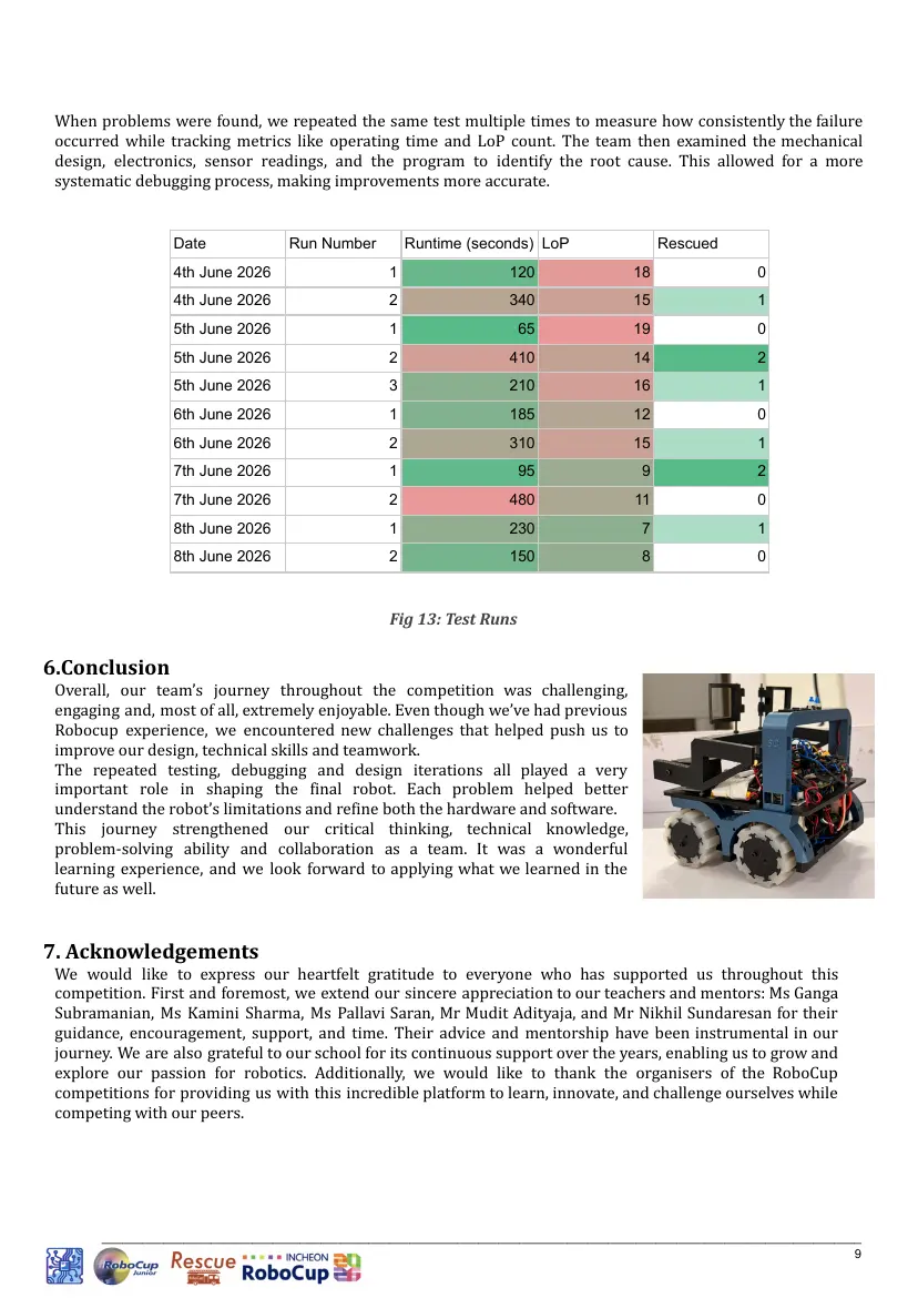
When problems were found, we repeated the same test multiple times to measure how consistently the failure
occurred while tracking metrics like operating time and LoP count. The team then examined the mechanical
design, electronics, sensor readings, and the program to identify the root cause. This allowed for a more
systematic debugging process, making improvements more accurate.
Date Run Number Runtime (seconds) LoP Rescued
4th June 2026 1 120 18 0
4th June 2026 2 340 15 1
5th June 2026 1 65 19 0
5th June 2026 2 410 14 2
5th June 2026 3 210 16 1
6th June 2026 1 185 12 0
6th June 2026 2 310 15 1
7th June 2026 1 95 9 2
7th June 2026 2 480 11 0
8th June 2026 1 230 7 1
8th June 2026 2 150 8 0
Fig 13: Test Runs
6.Conclusion
Overall, our team’s journey throughout the competition was challenging,
engaging and, most of all, extremely enjoyable. Even though we’ve had previous
Robocup experience, we encountered new challenges that helped push us to
improve our design, technical skills and teamwork.
The repeated testing, debugging and design iterations all played a very
important role in shaping the final robot. Each problem helped better
understand the robot’s limitations and refine both the hardware and software.
This journey strengthened our critical thinking, technical knowledge,
problem-solving ability and collaboration as a team. It was a wonderful
learning experience, and we look forward to applying what we learned in the
future as well.
7. Acknowledgements
We would like to express our heartfelt gratitude to everyone who has supported us throughout this
competition. First and foremost, we extend our sincere appreciation to our teachers and mentors: Ms Ganga
Subramanian, Ms Kamini Sharma, Ms Pallavi Saran, Mr Mudit Adityaja, and Mr Nikhil Sundaresan for their
guidance, encouragement, support, and time. Their advice and mentorship have been instrumental in our
journey. We are also grateful to our school for its continuous support over the years, enabling us to grow and
explore our passion for robotics. Additionally, we would like to thank the organisers of the RoboCup
competitions for providing us with this incredible platform to learn, innovate, and challenge ourselves while
competing with our peers.
_______________________________________________________________________________________________________________
9
8. References
Here is a list of references our team used while developing our robot. These include technical guides and
online discussions that helped us understand design, programming, and problem-solving. Each reference
provided useful information that influenced how we built and improved our robot
● We referred to the official Arduino forum for troubleshooting and code snippets.
○ Link: https://forum.arduino.c
● OpenMV documentation is used to implement code in the camera module.
○ Link: https://docs.openmv.io
● We referred to the Raspberry Pi forum for troubleshooting and for finding different kinds of libraries
○ https://forums.raspberrypi.com/viewtopic.php?t=241987
● Referred to the RCJ forum for Q&A.
○ Link: https://junior.forum.robocup.org/
● We also got our digital communication ratio from all the RoboCup International Teams and their runs, as
well as from some websites for hardware aspects
○ https://youtu.be/eP99Jd03Dmo?si=Ag0fRsJof6Hw0rEy
○ https://youtu.be/-4d62VtdYp8?si=P_m_5QFBx3QzH5gw
○ https://youtu.be/xN;CCSq1M0o4?si=kB50nhUO4vC6kkYr
○ https://www.youtube.com/watch?v=-EyZ6_YDfWE
● We referred to the RCJ community website for reference to the mats
○ https://rescue.rcj.cloud/events/2024/RoboCup2024/line/practice
9. Other Documents
● Poster: Robocup Internationals 2026 SO.pdf
● BOM: System Override - BOM
● Website: https://teamsystemoverride.com/
● Github: https://github.com/SystemOverride1
_______________________________________________________________________________________________________________
10
10 pages, rendered as images so they load quickly. The text above is the document's own, extracted from the PDF.
Source code
The team's own source code, 24 KB. It is a download rather than part of this page, because a zip is something you open on your computer. It comes from GitHub, which some school networks block.