NLO Rescue CRO Team
Document register
- Poster1 pagePublished
- Presentation videoYouTubePublished
- Bill of materials90 KBPublished
- Team description paper419 KBPublished
- Engineering journalNot shared
- Source code6 KB · GitHubPublished
Sharing each document is the team's decision. “Not shared” means this team chose not to publish it, or did not submit one — not that it is missing from the archive.
In their words
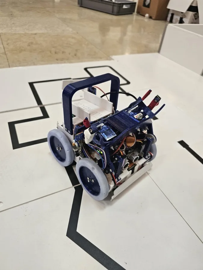
Our robot was designed and built specifically for the RoboCupJunior Rescue Line 2026 category. We started work on the 3D design and parts testing in September 2025. During development we built two different robots: the first one in December 2025 and the second one in March 2026. The robot is based on a modular architecture using a Teensy 4.1 microcontroller and a Raspberry Pi for vision processing. We use two cameras: one for line tracking and one for the evacuation zone. Both cameras are connected to the Raspberry Pi and programmed in OpenCV, allowing precise image processing. To keep the lighting stable regardless of the environment, we developed a custom diode-based lighting system around the line camera. All low-level control, including motors and sensors, is handled by the Teensy 4.1, while the Raspberry Pi processes visual data and runs a custom neural network for victim detection. The two controllers communicate using the UART protocol. The robot is built around a 3D printed chassis, a custom made PCB and sensors needed for the competition. Through development and testing, including multiple robot and PCB versions, we achieved a reliable and efficient robot capable of handling all challenges of the Rescue Line competition.
Image 1 (first robot)
Image 2 (second robot)
Poster
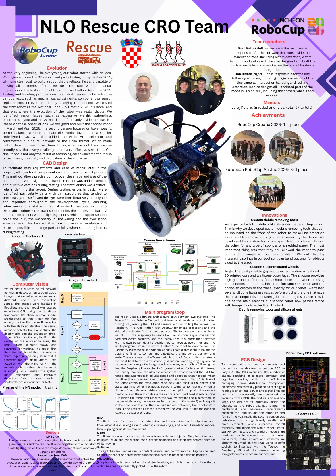
Read the text of this document — 1618 words
NLO Rescue CRO Team
Team members
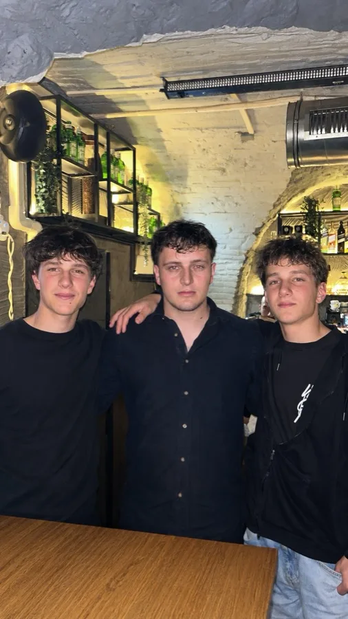
Sven Ridzak (left) -Sven leads the team and is
responsible for the software that runs inside the
evacuation zone, including victim detection, victim
handling and exit search. He also designed and built the
custom made PCB and worked on the overall hardware
Evolution integration.
At the very beginning, like everything, our robot started with an idea. Jan Ridzak (right) - Jan is responsible for the line
We began work on the 3D design and parts testing in September 2025, following software, including image processing of the
with one clear goal: to build a robot that is reliable, fast and capable of line camera, intersection handling and red line
solving all elements of the Rescue Line track without manual detection. He also designs all 3D printed parts of the
intervention. The first version of the robot was built in December 2025. robot in Fusion 360, including the chassis, wheels and
Testing and locating problems on this robot needed to be solved in mounts.
various ways, such as mechanical adjustments, component or sensor
replacements, or even completely changing the concept. We tested Mentors
the first robot at the National RoboCup Croatia 2026 in March, and Juraj Kolarić (middle) and Ivica Kolarić (far left)
that was where the evolution of the robot was really visible. We
identified major issues such as excessive weight, suboptimal Achievments
electronics layout and a PCB that did not fit cleanly inside the chassis.
Based on these observations, we designed and built the second robot RoboCup Croatia 2026- 1st place
in March and April 2026. The second version focused on lower weight,
better balance, a more compact electronics layout and a smaller,
redesigned PCB. We also added the Hailo AI accelerator and
reformatted our neural network to the Hailo format, which made
victim detection run in real time. Today, when we look back, we can
proudly say that every challenge and every effort was worth it. Our
final robot is not only the result of technological advancement but also
of teamwork, creativity and dedication of the entire team.
CAD Design
To facilitate easy adjustments and ease of repair later in the
European RoboCup Austria 2026- 3rd place
project, all structural components were chosen to be 3D printed.
This method allows precise control over the shape and size of the
components. We designed the chassis in Fusion 360 and Tinkercad,
and built two versions during testing. The first version was a critical
role in defining the layout. During testing, errors in design were
identified, particularly parts with thin structures that tended to
break easily. These flawed designs were then iteratively redesigned
and reprinted throughout the development cycle, ensuring
robustness and reliability in the final product. The robot is split into
two main sections – the lower section holds the motors, the battery
and the line camera with its lighting diodes, while the upper section Innovations
holds the PCB, the Raspberry Pi, the wiring and the evacuation Custom debris removing tools
zone camera. This layered structure improves accessibility and We expected a lot of debris like shredded papers, chopsticks...
makes it possible to change parts quickly when something breaks That is why we developed custom debris removing tools that can
during testing. be mounted on the front of the robot to make line detection
Lower section
Robot in Thinkercad easier and to remove slipping effects caused by the debris. We
Connection scheme developed two custom tools, one specialised for chopsticks and
the other for any type of sponges or shredded paper. The most
important thing was that they still allowed the robot to pass
bumps and ramps without any problem. We did that by
integrating springs in our tool so it can bend but only for objects
glued to the track.
Custom silicone-coated wheels
To get the best possible grip we designed custom wheels with a
3D printed core and a silicone outer layer. The silicone provides
Program flowchart high grip on the field surface, shock absorption when crossing
Computer Vision intersections and bumps, better performance on ramps and the
We trained a custom neural network option to customize the wheel exactly for our robot. We tested
for victim detection on around 2000 several silicone hardness values before picking the one that gave
images that we collected ourselves on the best compromise between grip and rolling resistance. This is
different Rescue Line evacuation one of the main reasons our second robot now passes ramps
zones. The images were labelled in
with bumps much better then the first.
Roboflow and the model was trained
Debris removing tools and silicon wheels
on a local GPU using the Ultralytics Main program loop
framework. We chose a small model
The robot uses a software architecture split between two systems. The
architecture so that it can run fast
Teensy 4.1 runs Arduino C++ code and handles all low-level control: motor
enough on the Raspberry Pi together
driving, PID, reading the IMU and sensors and controlling the servos. The
with the Hailo accelerator. The neural
Raspberry Pi 5 runs Python with OpenCV for image processing and the
network detects the live victims, the
Hailo AI accelerator for the neural network. The two systems communicate
dead victim and the collection (drop)
via UART — the Raspberry Pi sends the line position, angle, intersection
areas. After positioning itself in the
type and victim positions, and the Teensy uses this information together
centre of the evacuation zone, the with its own sensor data to decide how to move at every moment. The
robot starts spinning slowly and whole program runs in five states. In State 1 the robot follows the line. The
searches for victims. The robot first Raspberry Pi reads the line camera, applies a colour threshold to isolate the
finds the two live victims and rescues black line, finds its contour and calculates the line centre position and PCB in Easy EDA software
them together, and only after that it angle. These are sent to the Teensy, which runs a PID controller that steers
searches for the dead victim. Used the robot back to the centre smoothly. A custom diode lighting ring around PCB Design
together with the Hailo AI HAT, the the line camera keeps the image consistent in any room. While following the To accommodate various components and
model runs in real time while the robot line, the Raspberry Pi also checks for green markers for intersection turns, connectors, we designed a custom PCB in
is moving, which makes the system the Teensy monitors the ultrasonic sensor for obstacles and the IMU for EasyEDA. The PCB minimizes the number of
more responsive and improves ramps, and automatically adjusts speed and direction when needed. When cables, resulting in a more compact and
detection of victims close to walls – the silver line is detected, the robot stops and moves to State 2. In State 2 organized design, while also efficiently
the hardest case in our earlier tests. the robot enters the evacuation zone, positions itself in the centre and managing power distribution. Component
Progres of the NN model in training starts spinning while the neural network searches for victims. When a placement was carefully planned so that signal
victim is found, the robot drives towards it and picks it up with the arm — a routing is short and power and signal lines do
photodiode on the arm confirms the victim is captured. Next it enters State not cross unnecessarily. We developed two
3, in which the robot first rescues the two live victims and places them in versions of the PCB. The first version was too
the live victim area, then searches for the dead victim (state 2) and drops it large and did not fit optimally inside the
in the dead victim area. Once all victims are delivered, the robot enters chassis. As the robot changed shape, the
State 4 and uses the IR sensors to follow the wall until it finds the exit and mechanical and hardware requirements
leaves the evacuation zone. changed too, and so did the structure and Soldered PCB
IMU form of the PCB itself. The second version was
The IMU is used for precise turns, orientation and ramp detection. It helps the robot redesigned to be significantly smaller and
know when it is climbing a ramp, when it changes angle, and when it needs to recover more efficient, which improved overall
from slipping or unstable movement. reliability and made the whole robot lighter.
Sensors Lidars JST XH connectors and standard headers are
Line CAM The lidars are used to measure distance from walls and objects. They help the robot used for stable connections – the power
The line camera is used for detecting the black line, intersections, navigate inside the evacuation zone, detect obstacles and keep the correct distance converters, motor drivers and cameras are
green markers and the red line. It works together with our custom while moving. directly mounted on the PCB using specific
diode lighting, which keeps the image stable in different rooms andSwitches sockets to interface with the Teensy, the
lighting conditions. The switches are used as simple contact sensors and control inputs. They can be used Raspberry Pi and the sensors, ensuring
Evacuation Zone CAM to start the robot or detect when a mechanical part has reached a certain position. straightforward and secure connections.
The evacuation zone camera is used when the robot enters the Photodiode
evacuation zone. It gives the Raspberry Pi a wide view of the zone, so The photodiode is mounted on the victim handling arm. It is used to confirm that a
the neural network can detect live victims, dead victims and drop victim has been successfully picked up by the robot.
areas.
1 page, rendered as images so they load quickly. The text above is the document's own, extracted from the PDF.
Presentation video
Hosted on YouTube. The player loads only when you press play.
Bill of materials
Shown as the original PDF, because this one is smaller that way and its text stays selectable and searchable.
Team description paper
Shown as the original PDF, because this one is smaller that way and its text stays selectable and searchable.
Source code
The team's own source code, 6 KB. It is a download rather than part of this page, because a zip is something you open on your computer. It comes from GitHub, which some school networks block.