Brainbots
Document register
- Poster1 pagePublished
- Presentation videoYouTubePublished
- Bill of materials82 KBPublished
- Team description paper12 pagesPublished
- Engineering journalNot shared
- Source codeNot shared
Sharing each document is the team's decision. “Not shared” means this team chose not to publish it, or did not submit one — not that it is missing from the archive.
In their words
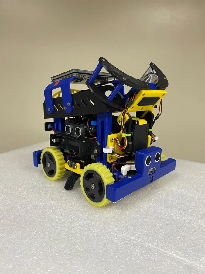
Our robot was developed for the RoboCupJunior Rescue Line competition and is built around a computer-vision architecture, where visual perception serves as the primary source of navigation and decision-making. Unlike traditional Rescue Line robots that rely heavily on dedicated line sensors, our system employs two cameras operating simultaneously: one for real-time line following and track analysis, and another for victim detection and evacuation-zone operations.
The robot uses a heterogeneous processing architecture consisting of an Arduino Mega for low-level control, sensor acquisition, and motor management, alongside a Raspberry Pi 5 equipped with a Hailo-8 AI accelerator for computer vision, artificial intelligence inference, and high-level decision-making. To improve navigation accuracy, we developed a bi-vectorial line-following system that combines information from near and far sections of the detected path, reducing premature steering corrections and improving performance in complex track layouts.
Victim recognition is performed using a custom-trained AI model accelerated by the Hailo-8, enabling reliable real-time detection. The robot also incorporates a custom 3D-printed modular chassis, a dedicated rescue mechanism with independently controlled arms, and a custom electronics board for power distribution and system integration. The combination of computer vision, artificial intelligence, and modular engineering enables the robot to achieve robust autonomous navigation and efficient evacuation-zone operations while maintaining high reliability under competition conditions.
Poster
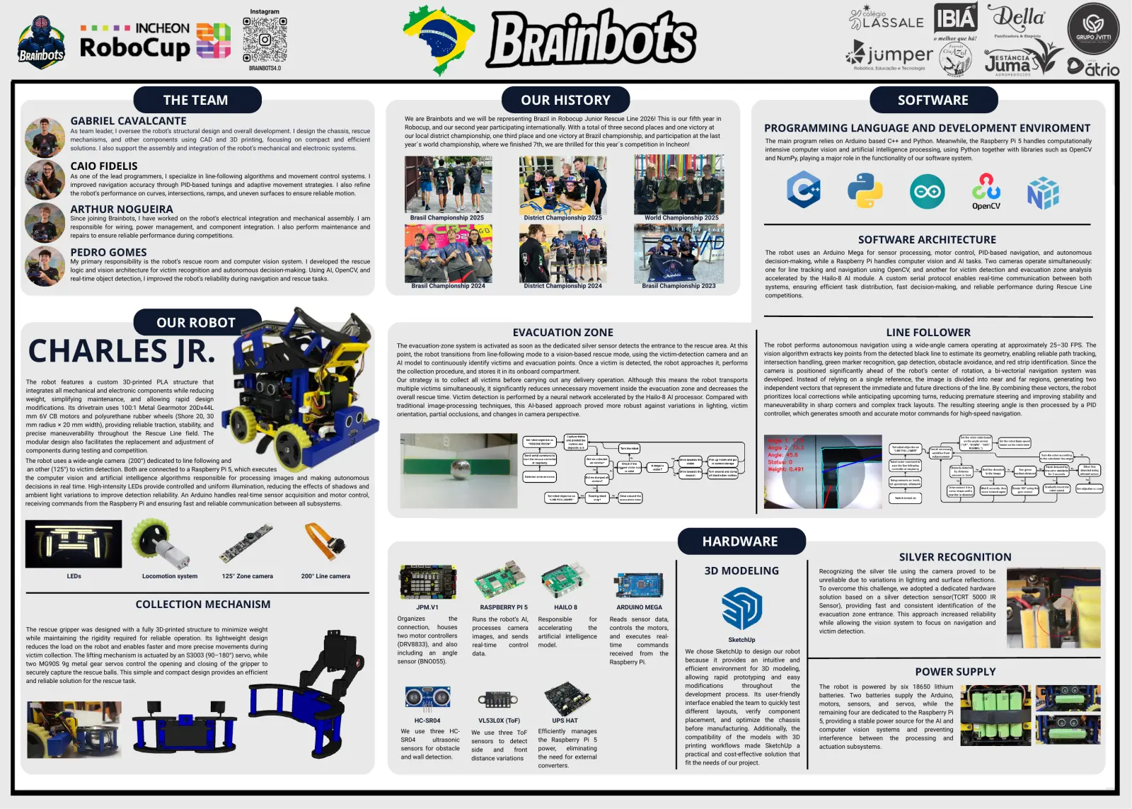
Read the text of this document — 1253 words
Instagram
THE TEAM OUR HISTORY SOFTWARE
GABRIEL CAVALCANTE We are Brainbots and we will be representing Brazil in Robocup Junior Rescue Line 2026! This is our fifth year in
As team leader, I oversee the robot’s structural design and overall development. I design the chassis, rescue
Robocup, and our second year participating internationally. With a total of three second places and one victory at PROGRAMMING LANGUAGE AND DEVELOPMENT ENVIROMENT
our local district championship, one third place and one victory at Brazil championship, and participation at the last
mechanisms, and other components using CAD and 3D printing, focusing on compact and efficient The main program relies on Arduino based C++ and Python. Meanwhile, the Raspberry Pi 5 handles computationally
year´s world championship, where we finished 7th, we are thrilled for this year´s competition in Incheon!
solutions. I also support the assembly and integration of the robot’s mechanical and electronic systems. intensive computer vision and artificial intelligence processing, using Python together with libraries such as OpenCV
and NumPy, playing a major role in the functionality of our software system.
CAIO FIDELIS
As one of the lead programmers, I specialize in line-following algorithms and movement control systems. I
improved navigation accuracy through PID-based tunings and adaptive movement strategies. I also refine
the robot’s performance on curves, intersections, ramps, and uneven surfaces to ensure reliable motion.
ARTHUR NOGUEIRA
Since joining Brainbots, I have worked on the robot’s electrical integration and mechanical assembly. I am Brasil Championship 2025 District Championship 2025 World Championship 2025
responsible for wiring, power management, and component integration. I also perform maintenance and
repairs to ensure reliable performance during competitions.
SOFTWARE ARCHITECTURE
PEDRO GOMES The robot uses an Arduino Mega for sensor processing, motor control, PID-based navigation, and autonomous
My primary responsibility is the robot’s rescue room and computer vision system. I developed the rescue decision-making, while a Raspberry Pi handles computer vision and AI tasks. Two cameras operate simultaneously:
logic and vision architecture for victim recognition and autonomous decision-making. Using AI, OpenCV, and one for line tracking and navigation using OpenCV, and another for victim detection and evacuation zone analysis
real-time object detection, I improved the robot’s reliability during navigation and rescue tasks. accelerated by the Hailo-8 AI module. A custom serial protocol enables real-time communication between both
Brasil Championship 2024 District Championship 2024 Brasil Championship 2023 systems, ensuring efficient task distribution, fast decision-making, and reliable performance during Rescue Line
competitions.
OUR ROBOT
EVACUATION ZONE LINE FOLLOWER
CHARLES JR. The evacuation-zone system is activated as soon as the dedicated silver sensor detects the entrance to the rescue area. At this
point, the robot transitions from line-following mode to a vision-based rescue mode, using the victim-detection camera and an
AI model to continuously identify victims and evacuation points. Once a victim is detected, the robot approaches it, performs
the collection procedure, and stores it in its onboard compartment.
The robot performs autonomous navigation using a wide-angle camera operating at approximately 25–30 FPS. The
vision algorithm extracts key points from the detected black line to estimate its geometry, enabling reliable path tracking,
intersection handling, green marker recognition, gap detection, obstacle avoidance, and red strip identification. Since the
camera is positioned significantly ahead of the robot’s center of rotation, a bi-vectorial navigation system was
The robot features a custom 3D-printed PLA structure that Our strategy is to collect all victims before carrying out any delivery operation. Although this means the robot transports developed. Instead of relying on a single reference, the image is divided into near and far regions, generating two
integrates all mechanical and electronic components while reducing multiple victims simultaneously, it significantly reduces unnecessary movement inside the evacuation zone and decreases the independent vectors that represent the immediate and future directions of the line. By combining these vectors, the robot
weight, simplifying maintenance, and allowing rapid design overall rescue time. Victim detection is performed by a neural network accelerated by the Hailo-8 AI processor. Compared with prioritizes local corrections while anticipating upcoming turns, reducing premature steering and improving stability and
modifications. Its drivetrain uses 100:1 Metal Gearmotor 20Dx44L traditional image-processing techniques, this AI-based approach proved more robust against variations in lighting, victim maneuverability in sharp corners and complex track layouts. The resulting steering angle is then processed by a PID
mm 6V CB motors and polyurethane rubber wheels (Shore 20, 30 orientation, partial occlusions, and changes in camera perspective. controller, which generates smooth and accurate motor commands for high-speed navigation.
mm radius × 20 mm width), providing reliable traction, stability, and
precise maneuverability throughout the Rescue Line field. The
modular design also facilitates the replacement and adjustment of
components during testing and competition.
The robot uses a wide-angle camera (200°) dedicated to line following and
an other (125°) to victim detection. Both are connected to a Raspberry Pi 5, which executes
the computer vision and artificial intelligence algorithms responsible for processing images and making autonomous
decisions in real time. High-intensity LEDs provide controlled and uniform illumination, reducing the effects of shadows and
ambient light variations to improve detection reliability. An Arduino handles real-time sensor acquisition and motor control,
receiving commands from the Raspberry Pi and ensuring fast and reliable communication between all subsystems.
HARDWARE
SILVER RECOGNITION
LEDs Locomotion system 125° Zone camera 200° Line camera
3D MODELING Recognizing the silver tile using the camera proved to be
unreliable due to variations in lighting and surface reflections.
To overcome this challenge, we adopted a dedicated hardware
solution based on a silver detection sensor(TCRT 5000 IR
COLLECTION MECHANISM JPM.V1 RASPBERRY PI 5 HAILO 8 ARDUINO MEGA Sensor), providing fast and consistent identification of the
evacuation zone entrance. This approach increased reliability
Organizes the Runs the robot’s AI, Responsible for Reads sensor data,
while allowing the vision system to focus on navigation and
The rescue gripper was designed with a fully 3D-printed structure to minimize weight connection, houses processes camera accelerating the controls the motors,
victim detection.
while maintaining the rigidity required for reliable operation. Its lightweight design two motor controllers images, and sends artificial intelligence and executes real-
SketchUp
reduces the load on the robot and enables faster and more precise movements during (DRV8833), and also real-time control model. time commands
including an angle data. received from the We chose SketchUp to design our robot
victim collection. The lifting mechanism is actuated by an S3003 (90–180°) servo, while
sensor (BNO055). Raspberry Pi. because it provides an intuitive and
two MG90S 9g metal gear servos control the opening and closing of the gripper to
securely capture the rescue balls. This simple and compact design provides an efficient
efficient environment for 3D modeling,
allowing rapid prototyping and easy
POWER SUPPLY
and reliable solution for the rescue task.
modifications throughout the The robot is powered by six 18650 lithium
development process. Its user-friendly batteries. Two batteries supply the Arduino,
interface enabled the team to quickly test motors, sensors, and servos, while the
different layouts, verify component remaining four are dedicated to the Raspberry Pi
HC-SR04 VL53L0X (ToF) UPS HAT placement, and optimize the chassis 5, providing a stable power source for the AI and
We use three HC- Efficiently manages before manufacturing. Additionally, the computer vision systems and preventing
We use three ToF
SR04 ultrasonic the Raspberry Pi 5 compatibility of the models with 3D interference between the processing and
sensors to detect
sensors for obstacle power, eliminating printing workflows made SketchUp a actuation subsystems.
side and front
and wall detection. the need for external practical and cost-effective solution that
distance variations
converters. fit the needs of our project.
1 page, rendered as images so they load quickly. The text above is the document's own, extracted from the PDF.
Presentation video
Hosted on YouTube. The player loads only when you press play.
Bill of materials
Shown as the original PDF, because this one is smaller that way and its text stays selectable and searchable.
Team description paper
Show the remaining 9 pages
Read the text of this document — 4213 words
ROBOCUPJUNIOR RESCUE LINE 2026
TEAM DESCRIPTION PAPER
Brainbots
Arthur Nogueira, Caio Fidelis, Gabriel Cavalcante and Pedro Gomes
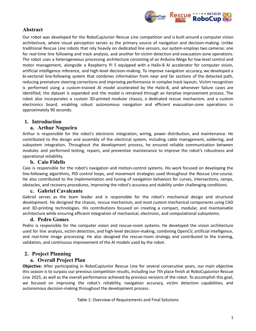
Abstract
Our robot was developed for the RoboCupJunior Rescue Line competition and is built around a computer vision
architecture, where visual perception serves as the primary source of navigation and decision-making. Unlike
traditional Rescue Line robots that rely heavily on dedicated line sensors, our system employs two cameras: one
for real-time line following and track analysis, and another for victim detection and evacuation-zone operations.
The robot uses a heterogeneous processing architecture consisting of an Arduino Mega for low-level control and
motor management, alongside a Raspberry Pi 5 equipped with a Hailo-8 AI accelerator for computer vision,
artificial intelligence inference, and high-level decision-making. To improve navigation accuracy, we developed a
bi-vectorial line-following system that combines information from near and far sections of the detected path,
reducing premature steering corrections and improving performance in complex track layouts. Victim recognition
is performed using a custom-trained AI model accelerated by the Hailo-8, and whenever failure cases are
identified, the dataset is expanded and the model is retrained through an iterative improvement process. The
robot also incorporates a custom 3D-printed modular chassis, a dedicated rescue mechanism, and a custom
electronics board, enabling robust autonomous navigation and efficient evacuation-zone operations in
approximately 90 seconds.
1. Introduction
a. Arthur Nogueira
Arthur is responsible for the robot’s electronic integration, wiring, power distribution, and maintenance. He
contributed to the design and assembly of the electrical system, including cable management, soldering, and
subsystem integration. Throughout the development process, he ensured reliable communication between
modules and performed testing, repairs, and preventive maintenance to improve the robot’s robustness and
operational reliability.
b. Caio Fidelis
Caio is responsible for the robot’s navigation and motion-control systems. His work focused on developing the
line-following algorithms, PID control loops, and movement strategies used throughout the Rescue Line course.
He also contributed to the implementation and tuning of navigation behaviors for curves, intersections, ramps,
obstacles, and recovery procedures, improving the robot’s accuracy and stability under challenging conditions.
c. Gabriel Cavalcante
Gabriel serves as the team leader and is responsible for the robot’s mechanical design and structural
development. He designed the chassis, rescue mechanism, and most custom mechanical components using CAD
and 3D-printing technologies. His contributions focused on creating a compact, modular, and maintainable
architecture while ensuring efficient integration of mechanical, electronic, and computational subsystems.
d. Pedro Gomes
Pedro is responsible for the computer vision and rescue-room systems. He developed the vision architecture
used for line analysis, victim detection, and high-level decision-making, combining OpenCV, artificial intelligence,
and real-time image processing. He also designed the rescue-room strategy and contributed to the training,
validation, and continuous improvement of the AI models used by the robot.
2. Project Planning
a. Overall Project Plan
Objective: After participating in RoboCupJunior Rescue Line for several consecutive years, our main objective
this season is to surpass our previous competition results, including our 7th place finish at RoboCupJunior Rescue
Line 2025, as well as the overall performance achieved by previous versions of the robot. To accomplish this goal,
we focused on improving the robot’s reliability, navigation accuracy, victim detection capabilities, and
autonomous decision-making throughout the development process.
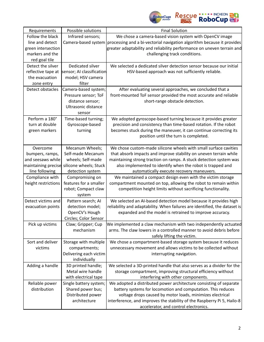
Table 1: Overview of Requirements and Final Solutions
1
Requirements Possible solutions Final Solution
Follow the black Infrared sensors; We chose a camera-based vision system with OpenCV image
line and detect Camera-based system processing and a bi-vectorial navigation algorithm because it provides
green intersection greater adaptability and reliability performance on uneven terrain and
markers and the challenging track conditions.
red goal tile
Detect the silver Dedicated silver We selected a dedicated silver detection sensor because our initial
reflective tape at sensor; AI classification HSV-based approach was not sufficiently reliable.
the evacuation model; HSV camera
zone entry filter
Detect obstacles Camera-based system; After evaluating several approaches, we concluded that a
Pressure sensor; ToF front-mounted ToF sensor provided the most accurate and reliable
distance sensor; short-range obstacle detection.
Ultrasonic distance
sensor
Perform a 180° Time-based turning; We adopted gyroscope-based turning because it provides greater
turn at double Gyroscope-based precision and consistency than time-based rotation. If the robot
green markers turning becomes stuck during the maneuver, it can continue correcting its
position until the turn is completed.
Overcome Mecanum Wheels; We chose custom-made silicone wheels with small surface cavities
bumpers, ramps, Self-made Mecanum that absorb impacts and improve stability on uneven terrain while
and seesaws while wheels; Self-made maintaining strong traction on ramps. A stuck detection system was
maintaining precise silicone wheels; Stuck also implemented to identify when the robot is trapped and
line following detection system automatically execute recovery maneuvers.
Compliance with Compromising on We maintained a compact design even with the victim storage
height restrictions features for a smaller compartment mounted on top, allowing the robot to remain within
robot; Compact claw competition height limits without sacrificing functionality.
system
Detect victims and Pattern search; AI We selected an AI-based detection model because it provides high
evacuation points detection model; reliability and adaptability. When failures are identified, the dataset is
OpenCV’s Hough expanded and the model is retrained to improve accuracy.
Circles; Color Sensor
Pick up victims Claw; Gripper; Cup We implemented a claw mechanism with two independently actuated
mechanism arms. The claw lowers in a controlled manner to avoid debris before
safely lifting the victim.
Sort and deliver Storage with multiple We chose a compartment-based storage system because it reduces
victims compartments; unnecessary movement and allows victims to be collected without
Delivering each victim interrupting navigation.
individually
Adding a handle 3D printed handle; We selected a 3D-printed handle that also serves as a divider for the
Metal wire handle storage compartment, improving structural efficiency without
with electrical tape interfering with other components.
Reliable power Single battery system; We adopted a distributed power architecture consisting of separate
distribution Shared power bus; battery systems for locomotion and computation. This reduces
Distributed power voltage drops caused by motor loads, minimizes electrical
architecture interference, and improves the stability of the Raspberry Pi 5, Hailo-8
accelerator, and control electronics.
2
Project Schedule: After classifying for RoboCup Junior Rescue Line 2026, we began the new season by reviewing
recordings and evaluating the performance of our robot in previous competitions, particularly our experience at
RoboCupJunior Rescue Line 2025. By analyzing both competition runs and testing sessions, we identified
limitations in the mechanical and software systems and used these findings to refine several of the solutions
presented in Table 1. Based on this analysis, we established a development schedule focused on improving
reliability, navigation performance, computer vision, and rescue-room operations. Tasks were distributed among
the four team members according to their areas of expertise: Arthur (A), Caio (C), Gabriel (G), and Pedro (P). This
structured planning enabled us to maintain steady progress throughout the season while ensuring that every
part of the robot could be carefully tested, refined, and fully integrated before the competition. A detailed
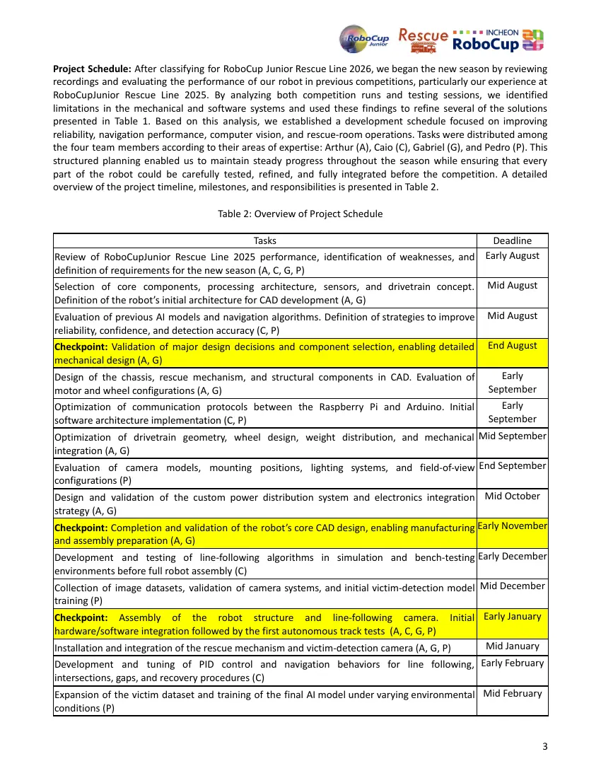
overview of the project timeline, milestones, and responsibilities is presented in Table 2.
Table 2: Overview of Project Schedule
Tasks Deadline
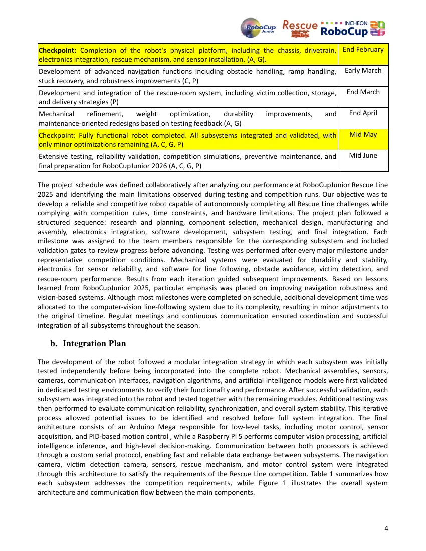
Review of RoboCupJunior Rescue Line 2025 performance, identification of weaknesses, and Early August
definition of requirements for the new season (A, C, G, P)
Selection of core components, processing architecture, sensors, and drivetrain concept. Mid August
Definition of the robot’s initial architecture for CAD development (A, G)
Evaluation of previous AI models and navigation algorithms. Definition of strategies to improve Mid August
reliability, confidence, and detection accuracy (C, P)
Checkpoint: Validation of major design decisions and component selection, enabling detailed End August
mechanical design (A, G)
Design of the chassis, rescue mechanism, and structural components in CAD. Evaluation of Early
motor and wheel configurations (A, G) September
Optimization of communication protocols between the Raspberry Pi and Arduino. Initial Early
software architecture implementation (C, P) September
Optimization of drivetrain geometry, wheel design, weight distribution, and mechanical Mid September
integration (A, G)
Evaluation of camera models, mounting positions, lighting systems, and field-of-view End September
configurations (P)
Design and validation of the custom power distribution system and electronics integration Mid October
strategy (A, G)
Checkpoint: Completion and validation of the robot’s core CAD design, enabling manufacturing Early November
and assembly preparation (A, G)
Development and testing of line-following algorithms in simulation and bench-testing Early December
environments before full robot assembly (C)
Collection of image datasets, validation of camera systems, and initial victim-detection model Mid December
training (P)
Checkpoint: Assembly of the robot structure and line-following camera. Initial Early January
hardware/software integration followed by the first autonomous track tests (A, C, G, P)
Installation and integration of the rescue mechanism and victim-detection camera (A, G, P) Mid January
Development and tuning of PID control and navigation behaviors for line following, Early February
intersections, gaps, and recovery procedures (C)
Expansion of the victim dataset and training of the final AI model under varying environmental Mid February
conditions (P)
3
Checkpoint: Completion of the robot’s physical platform, including the chassis, drivetrain, End February
electronics integration, rescue mechanism, and sensor installation. (A, G).
Development of advanced navigation functions including obstacle handling, ramp handling, Early March
stuck recovery, and robustness improvements (C, P)
Development and integration of the rescue-room system, including victim collection, storage, End March
and delivery strategies (P)
Mechanical refinement, weight optimization, durability improvements, and End April
maintenance-oriented redesigns based on testing feedback (A, G)
Checkpoint: Fully functional robot completed. All subsystems integrated and validated, with Mid May
only minor optimizations remaining (A, C, G, P)
Extensive testing, reliability validation, competition simulations, preventive maintenance, and Mid June
final preparation for RoboCupJunior 2026 (A, C, G, P)
The project schedule was defined collaboratively after analyzing our performance at RoboCupJunior Rescue Line
2025 and identifying the main limitations observed during testing and competition runs. Our objective was to
develop a reliable and competitive robot capable of autonomously completing all Rescue Line challenges while
complying with competition rules, time constraints, and hardware limitations. The project plan followed a
structured sequence: research and planning, component selection, mechanical design, manufacturing and
assembly, electronics integration, software development, subsystem testing, and final integration. Each
milestone was assigned to the team members responsible for the corresponding subsystem and included
validation gates to review progress before advancing. Testing was performed after every major milestone under
representative competition conditions. Mechanical systems were evaluated for durability and stability,
electronics for sensor reliability, and software for line following, obstacle avoidance, victim detection, and
rescue-room performance. Results from each iteration guided subsequent improvements. Based on lessons
learned from RoboCupJunior 2025, particular emphasis was placed on improving navigation robustness and
vision-based systems. Although most milestones were completed on schedule, additional development time was
allocated to the computer-vision line-following system due to its complexity, resulting in minor adjustments to
the original timeline. Regular meetings and continuous communication ensured coordination and successful
integration of all subsystems throughout the season.
b. Integration Plan
The development of the robot followed a modular integration strategy in which each subsystem was initially
tested independently before being incorporated into the complete robot. Mechanical assemblies, sensors,
cameras, communication interfaces, navigation algorithms, and artificial intelligence models were first validated
in dedicated testing environments to verify their functionality and performance. After successful validation, each
subsystem was integrated into the robot and tested together with the remaining modules. Additional testing was
then performed to evaluate communication reliability, synchronization, and overall system stability. This iterative
process allowed potential issues to be identified and resolved before full system integration. The final
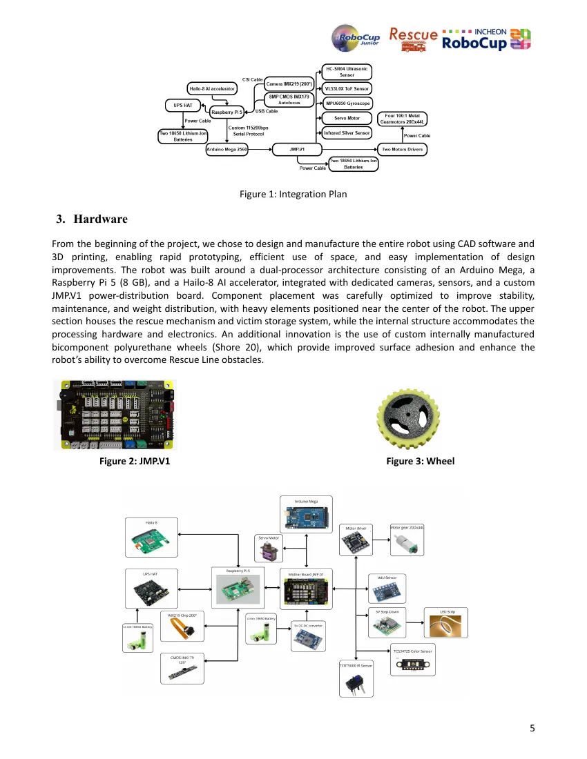
architecture consists of an Arduino Mega responsible for low-level tasks, including motor control, sensor
acquisition, and PID-based motion control , while a Raspberry Pi 5 performs computer vision processing, artificial
intelligence inference, and high-level decision-making. Communication between both processors is achieved
through a custom serial protocol, enabling fast and reliable data exchange between subsystems. The navigation
camera, victim detection camera, sensors, rescue mechanism, and motor control system were integrated
through this architecture to satisfy the requirements of the Rescue Line competition. Table 1 summarizes how
each subsystem addresses the competition requirements, while Figure 1 illustrates the overall system
architecture and communication flow between the main components.
4
Figure 1: Integration Plan
3. Hardware
From the beginning of the project, we chose to design and manufacture the entire robot using CAD software and
3D printing, enabling rapid prototyping, efficient use of space, and easy implementation of design
improvements. The robot was built around a dual-processor architecture consisting of an Arduino Mega, a
Raspberry Pi 5 (8 GB), and a Hailo-8 AI accelerator, integrated with dedicated cameras, sensors, and a custom
JMP.V1 power-distribution board. Component placement was carefully optimized to improve stability,
maintenance, and weight distribution, with heavy elements positioned near the center of the robot. The upper
section houses the rescue mechanism and victim storage system, while the internal structure accommodates the
processing hardware and electronics. An additional innovation is the use of custom internally manufactured
bicomponent polyurethane wheels (Shore 20), which provide improved surface adhesion and enhance the
robot’s ability to overcome Rescue Line obstacles.
Figure 2: JMP.V1 Figure 3: Wheel
5
Figure 4: Hardware diagram of all installed components
a. Mechanical Design and Manufacturing
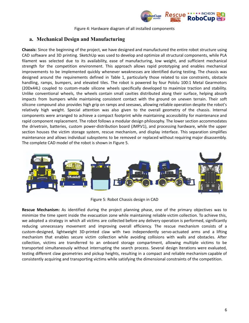
Chassis: Since the beginning of the project, we have designed and manufactured the entire robot structure using
CAD software and 3D printing. SketchUp was used to develop and optimize all structural components, while PLA
filament was selected due to its availability, ease of manufacturing, low weight, and sufficient mechanical
strength for the competition environment. This approach allows rapid prototyping and enables mechanical
improvements to be implemented quickly whenever weaknesses are identified during testing. The chassis was
designed around the requirements defined in Table 1, particularly those related to size constraints, obstacle
handling, ramps, bumpers, and elevated tiles. The robot is powered by four Pololu 100:1 Metal Gearmotors
(20Dx44L) coupled to custom-made silicone wheels specifically developed to maximize traction and stability.
Unlike conventional wheels, the wheels contain small cavities distributed along their surface, helping absorb
impacts from bumpers while maintaining consistent contact with the ground on uneven terrain. Their soft
silicone compound also provides high grip on ramps and seesaws, allowing reliable operation despite the robot's
relatively high weight. Special attention was also given to the overall geometry of the chassis. Internal
components were arranged to achieve a compact footprint while maintaining accessibility for maintenance and
rapid component replacement. The robot follows a modular design philosophy. The lower section accommodates
the drivetrain, batteries, custom power-distribution board (JMP.V1), and processing hardware, while the upper
section houses the victim storage system, rescue mechanism, and display interface. This separation simplifies
maintenance and allows individual subsystems to be removed or replaced without requiring major disassembly.
The complete CAD model of the robot is shown in Figure 5.
Figure 5: Robot Chassis design in CAD
Rescue Mechanism: As identified during the project planning phase, one of the primary objectives was to
minimize the time spent inside the evacuation zone while maintaining reliable victim collection. To achieve this,
we adopted a strategy in which all victims are collected before any delivery operation is performed, significantly
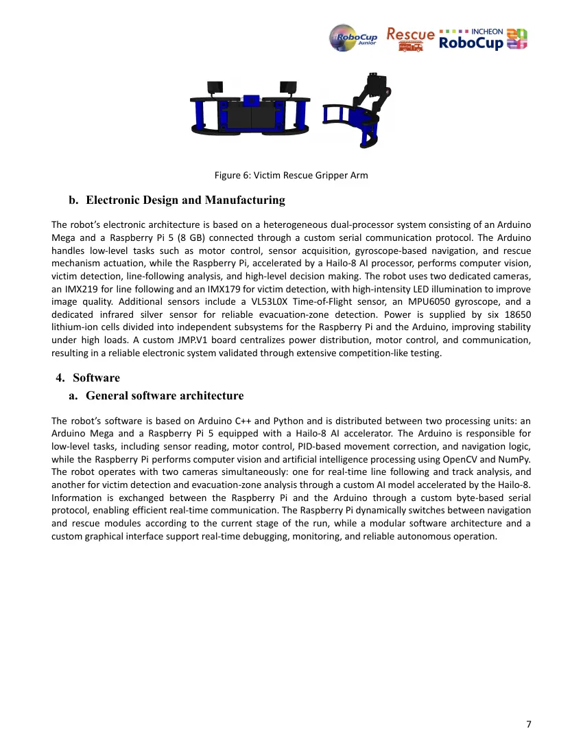
reducing unnecessary movement and improving overall efficiency. The rescue mechanism consists of a
custom-designed, lightweight 3D-printed claw with two independently servo-actuated arms and a lifting
mechanism that enables secure victim collection while avoiding collisions with walls and obstacles. After
collection, victims are transferred to an onboard storage compartment, allowing multiple victims to be
transported simultaneously without interrupting the search process. Several design iterations were evaluated,
testing different claw geometries and pickup heights, resulting in a compact and reliable mechanism capable of
consistently acquiring and transporting victims while satisfying the dimensional constraints of the competition.
6
Figure 6: Victim Rescue Gripper Arm
b. Electronic Design and Manufacturing
The robot’s electronic architecture is based on a heterogeneous dual-processor system consisting of an Arduino
Mega and a Raspberry Pi 5 (8 GB) connected through a custom serial communication protocol. The Arduino
handles low-level tasks such as motor control, sensor acquisition, gyroscope-based navigation, and rescue
mechanism actuation, while the Raspberry Pi, accelerated by a Hailo-8 AI processor, performs computer vision,
victim detection, line-following analysis, and high-level decision making. The robot uses two dedicated cameras,
an IMX219 for line following and an IMX179 for victim detection, with high-intensity LED illumination to improve
image quality. Additional sensors include a VL53L0X Time-of-Flight sensor, an MPU6050 gyroscope, and a
dedicated infrared silver sensor for reliable evacuation-zone detection. Power is supplied by six 18650
lithium-ion cells divided into independent subsystems for the Raspberry Pi and the Arduino, improving stability
under high loads. A custom JMP.V1 board centralizes power distribution, motor control, and communication,
resulting in a reliable electronic system validated through extensive competition-like testing.
4. Software
a. General software architecture
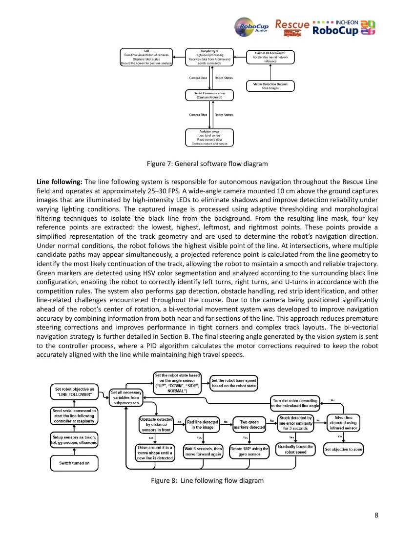
The robot’s software is based on Arduino C++ and Python and is distributed between two processing units: an
Arduino Mega and a Raspberry Pi 5 equipped with a Hailo-8 AI accelerator. The Arduino is responsible for
low-level tasks, including sensor reading, motor control, PID-based movement correction, and navigation logic,
while the Raspberry Pi performs computer vision and artificial intelligence processing using OpenCV and NumPy.
The robot operates with two cameras simultaneously: one for real-time line following and track analysis, and
another for victim detection and evacuation-zone analysis through a custom AI model accelerated by the Hailo-8.
Information is exchanged between the Raspberry Pi and the Arduino through a custom byte-based serial
protocol, enabling efficient real-time communication. The Raspberry Pi dynamically switches between navigation
and rescue modules according to the current stage of the run, while a modular software architecture and a
custom graphical interface support real-time debugging, monitoring, and reliable autonomous operation.
7
Figure 7: General software flow diagram
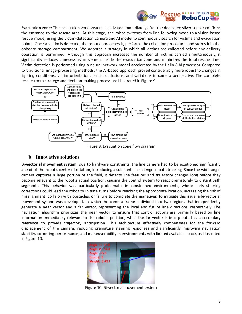
Line following: The line following system is responsible for autonomous navigation throughout the Rescue Line
field and operates at approximately 25–30 FPS. A wide-angle camera mounted 10 cm above the ground captures
images that are illuminated by high-intensity LEDs to eliminate shadows and improve detection reliability under
varying lighting conditions. The captured image is processed using adaptive thresholding and morphological
filtering techniques to isolate the black line from the background. From the resulting line mask, four key
reference points are extracted: the lowest, highest, leftmost, and rightmost points. These points provide a
simplified representation of the track geometry and are used to determine the robot’s navigation direction.
Under normal conditions, the robot follows the highest visible point of the line. At intersections, where multiple
candidate paths may appear simultaneously, a projected reference point is calculated from the line geometry to
identify the most likely continuation of the track, allowing the robot to maintain a smooth and reliable trajectory.
Green markers are detected using HSV color segmentation and analyzed according to the surrounding black line
configuration, enabling the robot to correctly identify left turns, right turns, and U-turns in accordance with the
competition rules. The system also performs gap detection, obstacle handling, red strip identification, and other
line-related challenges encountered throughout the course. Due to the camera being positioned significantly
ahead of the robot’s center of rotation, a bi-vectorial movement system was developed to improve navigation
accuracy by combining information from both near and far sections of the line. This approach reduces premature
steering corrections and improves performance in tight corners and complex track layouts. The bi-vectorial
navigation strategy is further detailed in Section B. The final steering angle generated by the vision system is sent
to the controller process, where a PID algorithm calculates the motor corrections required to keep the robot
accurately aligned with the line while maintaining high travel speeds.
Figure 8: Line following flow diagram
8
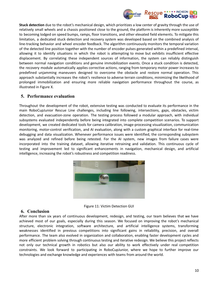
Evacuation zone: The evacuation-zone system is activated immediately after the dedicated silver sensor confirms
the entrance to the rescue area. At this stage, the robot switches from line-following mode to a vision-based
rescue mode, using the victim-detection camera and AI model to continuously search for victims and evacuation
points. Once a victim is detected, the robot approaches it, performs the collection procedure, and stores it in the
onboard storage compartment. We adopted a strategy in which all victims are collected before any delivery
operation is performed. Although this approach increases the number of victims carried simultaneously, it
significantly reduces unnecessary movement inside the evacuation zone and minimizes the total rescue time.
Victim detection is performed using a neural-network model accelerated by the Hailo-8 AI processor. Compared
to traditional image-processing methods, the AI-based approach proved considerably more robust to changes in
lighting conditions, victim orientation, partial occlusions, and variations in camera perspective. The complete
rescue-room strategy and decision-making process are illustrated in Figure 9.
Figure 9: Evacuation zone flow diagram
b. Innovative solutions
Bi-vectorial movement system: due to hardware constraints, the line camera had to be positioned significantly
ahead of the robot's center of rotation, introducing a substantial challenge in path tracking. Since the wide-angle
camera captures a large portion of the field, it detects line features and trajectory changes long before they
become relevant to the robot's actual position, causing the control system to react prematurely to distant path
segments. This behavior was particularly problematic in constrained environments, where early steering
corrections could lead the robot to initiate turns before reaching the appropriate location, increasing the risk of
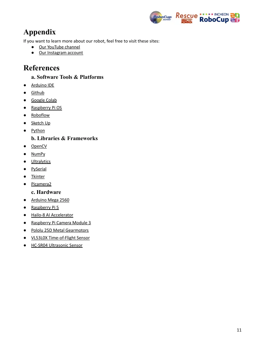
misalignment, collision with obstacles, or failure to complete the maneuver. To mitigate this issue, a bi-vectorial
movement system was developed, in which the camera frame is divided into two regions that independently
generate a near vector and a far vector, representing the local and future line directions, respectively. The
navigation algorithm prioritizes the near vector to ensure that control actions are primarily based on line
information immediately relevant to the robot's position, while the far vector is incorporated as a secondary
reference to provide trajectory anticipation. This architecture effectively compensates for the forward
displacement of the camera, reducing premature steering responses and significantly improving navigation
stability, cornering performance, and maneuverability in environments with limited available space, as illustrated
in Figure 10.
Figure 10: Bi-vectorial movement system
9
Stuck detection due to the robot’s mechanical design, which prioritizes a low center of gravity through the use of
relatively small wheels and a chassis positioned close to the ground, the platform is inherently more susceptible
to becoming lodged on speed bumps, ramps, floor transitions, and other elevated field elements. To mitigate this
limitation, a dedicated stuck detection and recovery system was developed based on the combined analysis of
line-tracking behavior and wheel encoder feedback. The algorithm continuously monitors the temporal variation
of the detected line position together with the number of encoder pulses generated within a predefined interval,
allowing it to identify situations in which the robot is attempting to move but exhibits insufficient effective
displacement. By correlating these independent sources of information, the system can reliably distinguish
between normal navigation conditions and genuine immobilization events. Once a stuck condition is detected,
the recovery module automatically applies corrective actions, ranging from temporary motor power increases to
predefined unjamming maneuvers designed to overcome the obstacle and restore normal operation. This
approach substantially increases the robot’s resilience to adverse terrain conditions, minimizing the likelihood of
prolonged immobilization and ensuring more reliable navigation performance throughout the course, as
illustrated in Figure X.
5. Performance evaluation
Throughout the development of the robot, extensive testing was conducted to evaluate its performance in the
main RoboCupJunior Rescue Line challenges, including line following, intersections, gaps, obstacles, victim
detection, and evacuation-zone operation. The testing process followed a modular approach, with individual
subsystems evaluated independently before being integrated into complete competition scenarios. To support
development, we created dedicated tools for camera calibration, image-processing visualization, communication
monitoring, motor-control verification, and AI evaluation, along with a custom graphical interface for real-time
debugging and data visualization. Whenever performance issues were identified, the corresponding subsystem
was analyzed and refined before being retested. For the AI system, new images from failure cases were
incorporated into the training dataset, allowing iterative retraining and validation. This continuous cycle of
testing and improvement led to significant enhancements in navigation, mechanical design, and artificial
intelligence, increasing the robot’s robustness and competition readiness.
Figure 11: Victim Detection GUI
6. Conclusion
After more than six years of continuous development, redesign, and testing, our team believes that we have
achieved most of our goals, especially during this season. We focused on improving the robot’s mechanical
structure, electronic integration, software architecture, and artificial intelligence systems, transforming
weaknesses identified in previous competitions into significant gains in reliability, precision, and overall
performance. The team also evolved in organization and collaboration, enabling faster development cycles and
more efficient problem solving through continuous testing and iterative redesign. We believe this project reflects
not only our technical growth in robotics but also our ability to work effectively under real competition
constraints. We look forward to participating in RoboCupJunior, where we hope to further improve our
technologies and exchange knowledge and experiences with teams from around the world.
10
Appendix
If you want to learn more about our robot, feel free to visit these sites:
● Our YouTube channel
● Our Instagram account
References
a. Software Tools & Platforms
● Arduino IDE
● Github
● Google Colab
● Raspberry Pi OS
● Roboflow
● Sketch Up
● Python
b. Libraries & Frameworks
● OpenCV
● NumPy
● Ultralytics
● PySerial
● Tkinter
● Picamera2
c. Hardware
● Arduino Mega 2560
● Raspberry Pi 5
● Hailo-8 AI Accelerator
● Raspberry Pi Camera Module 3
● Pololu 25D Metal Gearmotors
● VL53L0X Time-of-Flight Sensor
● HC-SR04 Ultrasonic Sensor
11
12 pages, rendered as images so they load quickly. The text above is the document's own, extracted from the PDF.