
Antares
Document register
- Poster1 pagePublished
- Presentation videoYouTubePublished
- Bill of materials1 pagePublished
- Team description paper17 pagesPublished
- Engineering journalNot shared
- Source code4 KB · GitHubPublished
Sharing each document is the team's decision. “Not shared” means this team chose not to publish it, or did not submit one — not that it is missing from the archive.
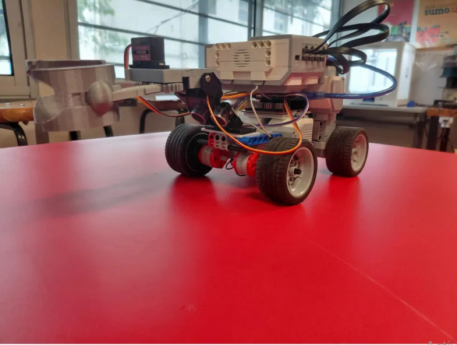
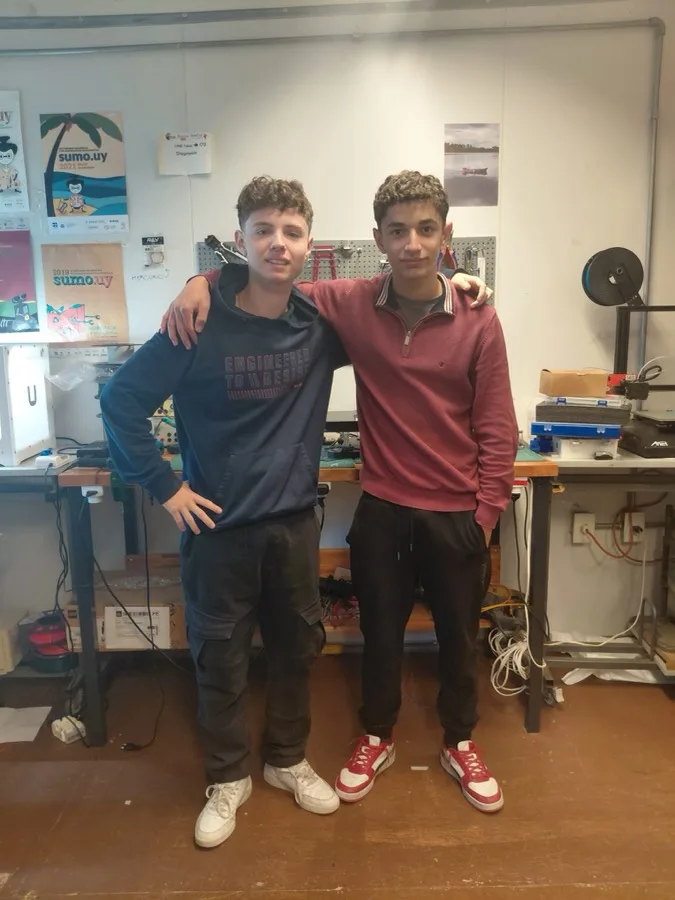
In their words
This is our first time participating in RoboCup, so we have no prior
experience in this competition. Regarding the robot, we decided to use a
QTR-8A (Arduino light sensor) connected to an Arduino Nano,
communicating with an EV3.We also used Lego color sensors for green
detection, which we were also going to use for line following, but we
realized that the color change to infrared could freeze the program, so
we opted to change the method for line following.
We learned a lot through trial and error, constantly changing our ideas
until we felt it could handle the challenge.
Now, with this sensor, it receives more information about the line, which
significantly improves its tracking. It's much more precise and offers
many advantages. It's more complex to prevent the robot from getting
stuck, and it handles different challenges on the line better. We used four
motors, which operate synchronously, with the rear motors following their
respective front motors. The power supply was changed to an EV3
battery that provides a constant 9V. Inclined and declined planes are
much easier to navigate with all four motors. We had this problem at the
beginning of the work for this competition and we worked to solve it,
coming to the conclusion that we needed four motors.
Poster
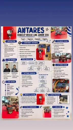
1 page, rendered as images so they load quickly. This document has no text layer — the words in it are part of the image.
Presentation video
Hosted on YouTube. The player loads only when you press play.
Bill of materials
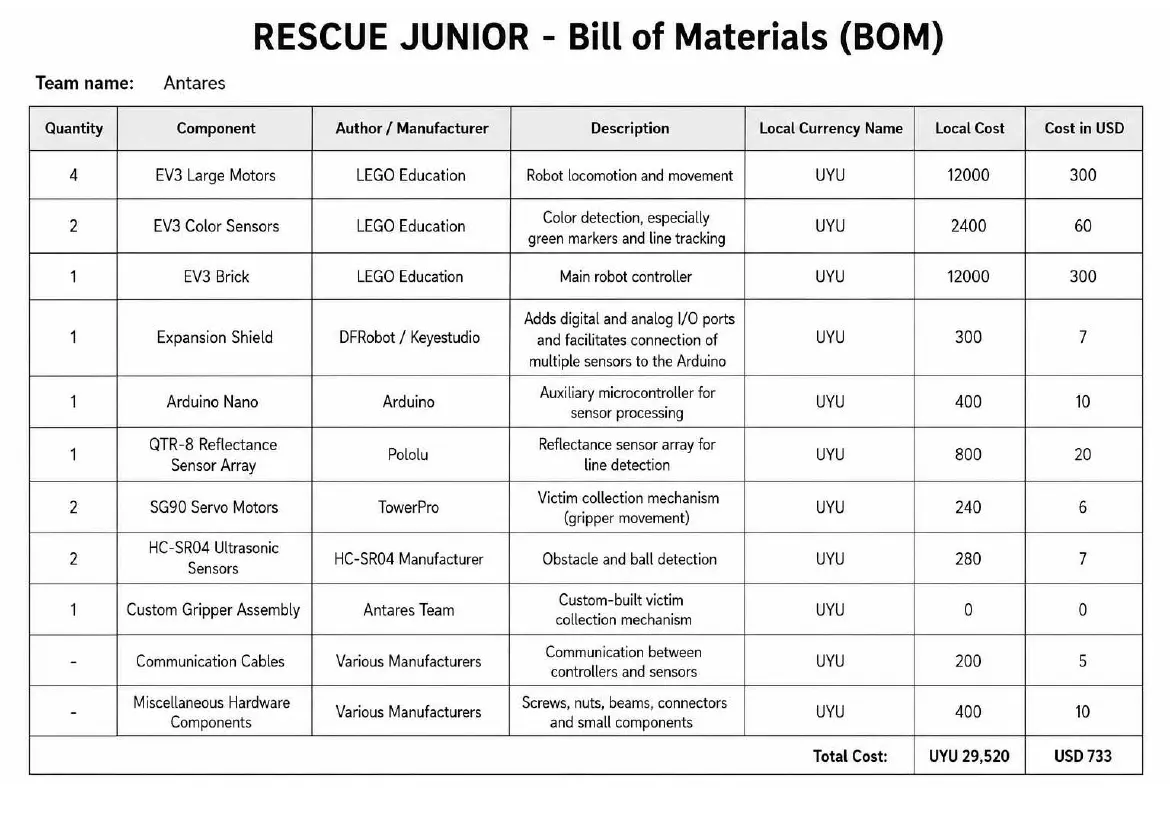
1 page, rendered as images so they load quickly. This document has no text layer — the words in it are part of the image.
Team description paper
Show the remaining 14 pages
Read the text of this document — 3011 words
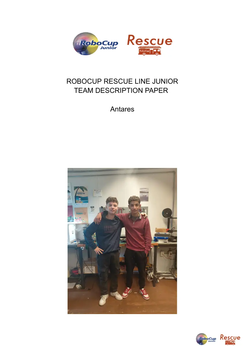
ROBOCUP RESCUE LINE JUNIOR
TEAM DESCRIPTION PAPER
Antares
General information for this template
● This template contains the structure for your Team Description Paper.
Please look into the official rubrics posted on the official RoboCup
website and the community website to see which areas of your TDP will
be scored.
● The document should be a maximum of 10 pages long (from Abstract
to Conclusion). Please keep the formatting (font size and type, margins,
line spacing, etc.), number figures and tables from this template. All text
in blue is included for clarity and can be removed. Text in black must
remain. It’s not necessary to maintain the bullet format. You may write
continuous paragraphs within sections.
● Use diagrams, flow charts, etc. throughout this document to better
illustrate your work.
● Submit the TDP as a PDF file.
● The competition organizer might ask the team to submit the TDP in a
web form. The details for this format would be shared by the competition
organizer.
Abstract
● Abstract should be between 150-250 words. Describe your robot, its
main capabilities and what sets it apart from competitors. Do not
describe your RoboCupJunior Rescue sub-league in detail.
This is our first time participating in RoboCup, so we have no prior
experience in this competition. Regarding the robot, we decided to use a
QTR-8A (Arduino light sensor) connected to an Arduino Nano,
communicating with an EV3.We also used Lego color sensors for green
detection, which we were also going to use for line following, but we
realized that the color change to infrared could freeze the program, so
we opted to change the method for line following.
We learned a lot through trial and error, constantly changing our ideas
until we felt it could handle the challenge.
Now, with this sensor, it receives more information about the line, which
significantly improves its tracking. It's much more precise and offers
many advantages. It's more complex to prevent the robot from getting
stuck, and it handles different challenges on the line better. We used four
motors, which operate synchronously, with the rear motors following their
respective front motors. The power supply was changed to an EV3
battery that provides a constant 9V. Inclined and declined planes are
much easier to navigate with all four motors. We had this problem at the
beginning of the work for this competition and we worked to solve it,
coming to the conclusion that we needed four motors.
1. Introduction
a. Team
Camilo González: I'm sixteen years old and from Canelones, Uruguay. I
started competing in robotics in 2025 with a national SUMO tournament.
This is my first time participating in RoboCup. I'm the captain of Team
Antares, and my role focuses more on the software, claw design, and
robot programming, but we both try to complement each other and do
whatever is necessary.
Ismael Bimonte: I'm sixteen years old and from Canelones, Uruguay. I
started competing in robotics in 2025 with a national SUMO tournament.
This is my first time participating in a RoboCup. My main responsibilities
are focused on the robot's hardware, as well as programming and
assembling its different parts.
2. Project Planning
a. Overall Project Plan
● Describe your team’s objective for the competition 2 ○ Define requirements that
your robot and team must meet based on constraints (i.e. physical constraints, time
constraints, competition rules, etc.).
● Describe the overall project plan ○ Highlight key milestones with a project
schedule/timeline (i.e. include deadlines) ○ Description of each milestone ○
Associate each milestone with a function/team member ○ Include gates to review
project progress (if needed)
● Explain how the team agreed on the schedule/plan, examples include: ○ Include
analysis of task and competition constraints ○ What is the sequence of milestones
and why (i.e. building mechanical robot then programming software) ○ What
conditions will be tested during each iteration ○ Impact of past performance on
subsequent iterations/runs
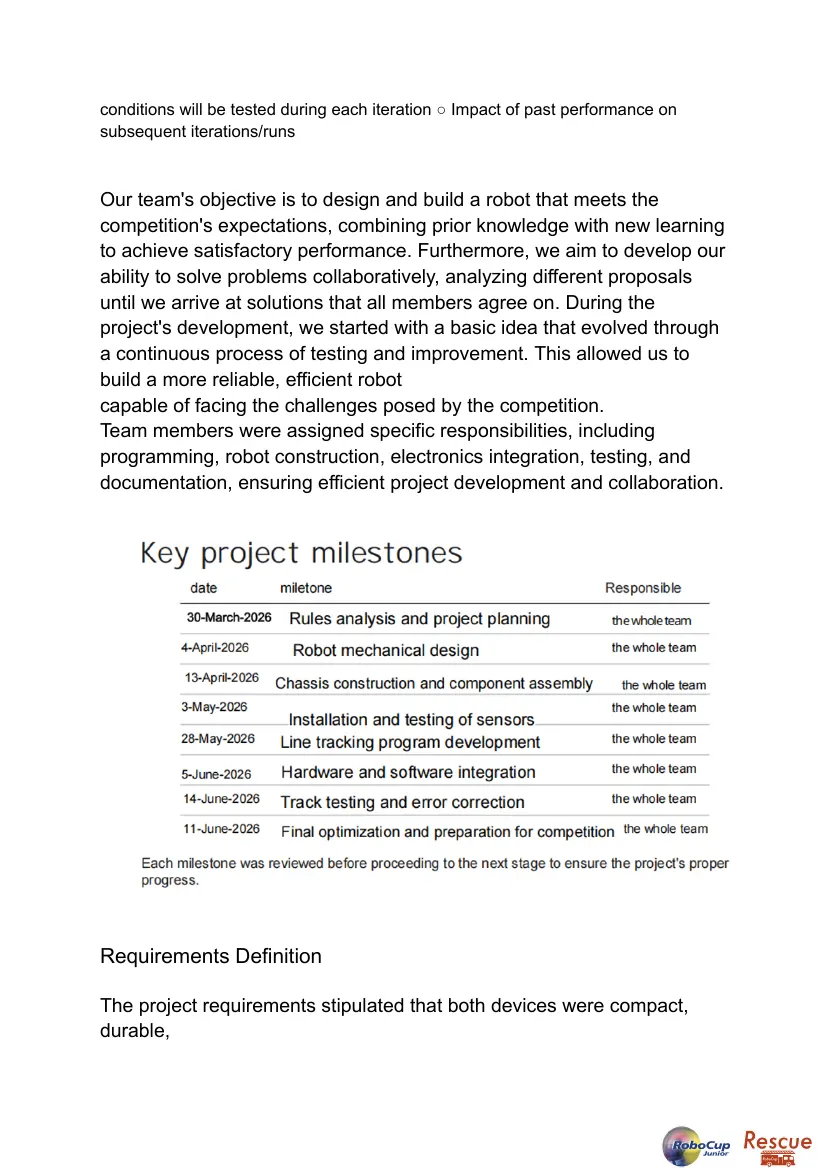
Our team's objective is to design and build a robot that meets the
competition's expectations, combining prior knowledge with new learning
to achieve satisfactory performance. Furthermore, we aim to develop our
ability to solve problems collaboratively, analyzing different proposals
until we arrive at solutions that all members agree on. During the
project's development, we started with a basic idea that evolved through
a continuous process of testing and improvement. This allowed us to
build a more reliable, efficient robot
capable of facing the challenges posed by the competition.
Team members were assigned specific responsibilities, including
programming, robot construction, electronics integration, testing, and
documentation, ensuring efficient project development and collaboration.
Requirements Definition
The project requirements stipulated that both devices were compact,
durable,
and easy to repair during the competition. It also had to be of an
approval
size to allow it to move easily around the track and see come the various
challenges.
Development time was also taken into account.The goal was to build a
fast and efficient robot, capable of meeting all the challenges without
speed affecting its performance reliability.
The competition rules served as a guide for the project's
organization.The robot had to operate completely
autonomously,recognize intersections,
identify and classify targets,and,most importantly,follow the linea
and efficiently.
Integration Plan
To correctly position the motors, several tests and adjustments were
necessary to find a configuration that maintained a compact, stable, and
efficient structure. Subsequently, the sensors, including the line-following
assembly, were installed on the same base, optimizing the available
space to incorporate the EV3 Brick, the Arduino Nano, and the gripping
mechanism.
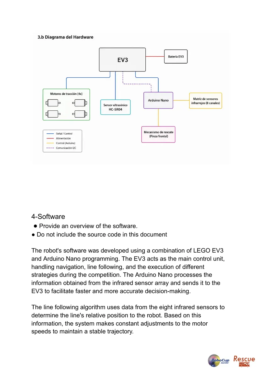
The LEGO components communicate through the EV3 Brick, while the
EV3 connects to the Arduino Nano via USB serial communication. This
integration allowed combining the capabilities of both platforms,
expanding the number of sensors and devices that could be used and
avoiding the limitations of a single controller. During the integration
process, each component was individually tested before being
incorporated into the complete system. Once the robot was assembled,
functional tests were performed to verify communication between the
devices, sensor readings, and the correct operation of the movement
and rescue mechanisms.
3-Hardware
● Give a high-level overview of the hardware design of your robot
● Highlight important features and talk about how everything works together
Our robot uses a hybrid architecture that combines the LEGO
Mindstorms EV3 platform with an Arduino Nano board. This
configuration allows us to leverage the robustness and reliability of the
EV3 system along with the flexibility that Arduino offers for integrating
custom sensors and electronic components.
The EV3 acts as the main control unit, while the Arduino Nano
processes the information from the infrared sensor array installed on the
front of the robot. Both devices work in coordination to enable precise
navigation and a rapid response to the various situations that may arise
during competition.
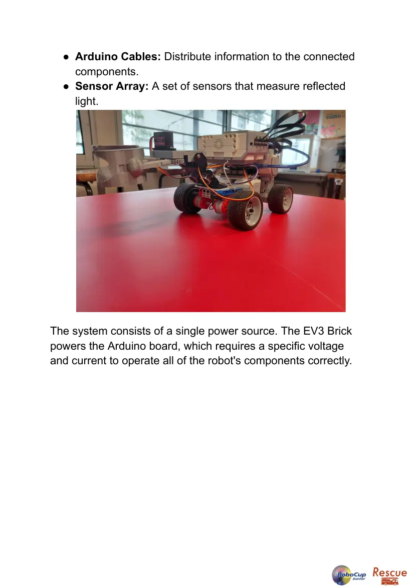
The robot features a structure based on LEGO Technic pieces
complemented by 3D-printed components. It also has a four-wheel
configuration to improve stability and weight distribution, as well as a
front gripper actuated by a servo motor.
Overall, the hardware was designed to be robust, modular, and
adaptable, facilitating both maintenance and future upgrades.
Our robot uses a hybrid architecture that combines the LEGO
Mindstorms EV3 platform with an Arduino Nano board. This
configuration allows us to leverage the robustness and reliability of the
EV3 system along with the flexibility that Arduino offers for integrating
custom sensors and electronic components.
The EV3 acts as the main control unit, while the Arduino Nano
processes the information from the infrared sensor array installed on the
front of the robot. Both devices work in coordination to enable precise
navigation and a rapid response to the various situations that may arise
during competition.
The robot features a structure based on LEGO Technic pieces
complemented by 3D-printed components. It also has a four-wheel
configuration to improve stability and weight distribution, as well as a
front gripper actuated by a servo motor.
Overall, the hardware was designed to be robust, modular, and
adaptable, facilitating both maintenance and future upgrades.
Mechanical Design and Manufacturing
● Provide a detailed overview of each aspect of the robot’s mechanical
design. Notably:
● Main Structure
● Actuators and Power Train
● Subassemblies/modules, etc.
● Rescue mechanism (Line only)
● Provide drawings, diagrams, or images to support your explanations
and reasoning for your design choices. Reference requirements outlined
during the project planning
● Explain the testing procedures used to validate the design. Include
relevant testing data.
● Highlight innovative and unusual solutions/approaches. Link back to
constraints and requirements.
a.
The main structure was built using LEGO Technic pieces, selected for
their strength, modularity, and ease of assembly. This approach allowed
for rapid modifications during the robot's design, testing, and opti}ization
phases.
The locomotion system consists of four wheels, providing stability and
balanced weight distribution. This configuration improves movement
precision and facilitates navigation through the various challenges of the
course.
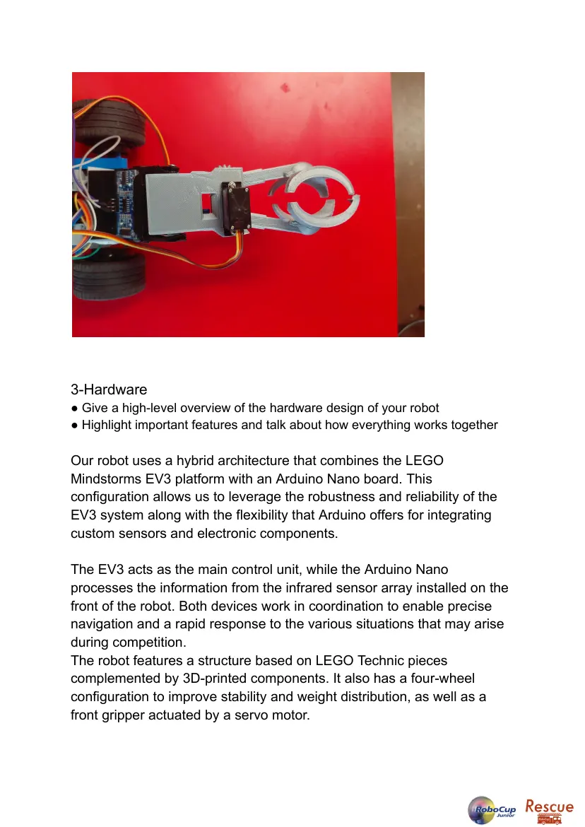
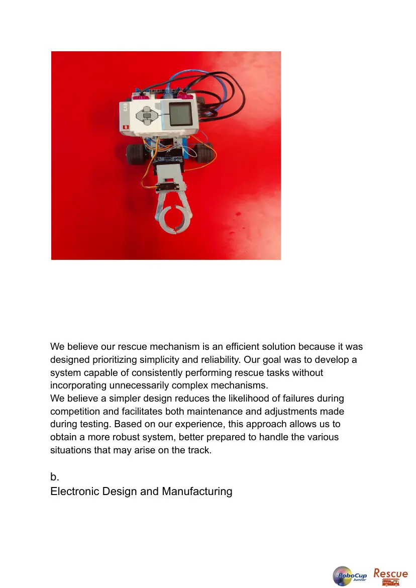
In addition, the robot incorporates a 3D-printed rescue mechanism on
the front. The mechanism comprises two symmetrical arms powered by
an MG90S servo motor and a gear system that transmits movement,
enabling precise capture of victims. The use of 3D-printed parts resulted
in a lightweight, strong, and easily customizable design.
The combination of LEGO elements and 3D-printed components allowed
for the development of a robust mechanical structure adaptable to future
modifications. Our robot evolved over the months. The initial concept
involved a robot with two motors and a caster wheel. Later, we had to
add two more wheels because the robot couldn't climb the inclined
plates.
We believe our rescue mechanism is an efficient solution because it was
designed prioritizing simplicity and reliability. Our goal was to develop a
system capable of consistently performing rescue tasks without
incorporating unnecessarily complex mechanisms.
We believe a simpler design reduces the likelihood of failures during
competition and facilitates both maintenance and adjustments made
during testing. Based on our experience, this approach allows us to
obtain a more robust system, better prepared to handle the various
situations that may arise on the track.
b.
Electronic Design and Manufacturing
● Provide a detailed overview of each aspect of the robot’s electronic
design and explain the used tools. Notably:
● Sensors used
● Main controller
● Power subsystem
● Actuators, etc
. ● Provide drawings, diagrams, or images to support your explanations
and reasoning for your design choices. Reference requirements outlined
during the project planning.
● Explain the testing procedures used to validate the design. Include
relevant testing data.
● Highlight innovative and unusual solutions/approaches. Link back to
constraints and requirements.
● EV3 Infrared Sensor: Responsible for detecting
obstacles.
● EV3 Color Sensor: Responsible for recognizing colors
through reflection (green, red, silver, black, and white).
● EV3 Motors: Responsible for the robot's movement along
the track.
● EV3 Brick: Runs the program that allows the robot to
process information and respond to different stimuli.
● EV3 Parts: Form the robot's structure by combining with
the components mentioned above.
● EV3 Cables: Responsible for transmitting information
between components.
● USB Serial Connection: Allows reliable communication
between the EV3 and the Arduino.
● EV3 Wheels: Work together with the motors to move the
robot.
● Arduino Nuno: Sends and receives information from the
different components.
● Servo Motors: Help collect and distribute the victims.
● Arduino Cables: Distribute information to the connected
components.
● Sensor Array: A set of sensors that measure reflected
light.
The system consists of a single power source. The EV3 Brick
powers the Arduino board, which requires a specific voltage
and current to operate all of the robot's components correctly.
4-Software
● Provide an overview of the software.
● Do not include the source code in this document
The robot's software was developed using a combination of LEGO EV3
and Arduino Nano programming. The EV3 acts as the main control unit,
handling navigation, line following, and the execution of different
strategies during the competition. The Arduino Nano processes the
information obtained from the infrared sensor array and sends it to the
EV3 to facilitate faster and more accurate decision-making.
The line following algorithm uses data from the eight infrared sensors to
determine the line's relative position to the robot. Based on this
information, the system makes constant adjustments to the motor
speeds to maintain a stable trajectory.
In addition, the software incorporates routines for obstacle detection
using the ultrasonic sensor and for controlling the rescue mechanism.
Communication between the EV3 and the Arduino allows both systems
to work in a coordinated manner, exchanging information in real time
throughout the course.
The software design focused on simplicity, reliability, and ease of
adjustment, allowing for rapid modifications during the testing and
optimization phases.
General software architecture
● Describe the general structure of your software
● Use diagrams and flowcharts to illustrate your explanations
● Explain how the software/code solves any problems that arose during
integration
● Describe the tools that your team used or developed (e.g. libraries,
algorithms, AI models)
b.
The robot's software was organized in a modular fashion to facilitate its
development, maintenance, and adjustment during testing. The system
is divided into two main parts: the program running on the LEGO EV3
and the program running on the Arduino Nano.
The Arduino Nano is responsible for reading and processing the infrared
sensor array. Once the line position information is obtained, this data is
sent to the EV3 via communication between the two devices.
The EV3, in turn, receives the sensor information and executes the
robot's main functions. These include line following, control of the drive
motors, obstacle detection using the ultrasonic sensor, and activation of
the rescue mechanism when necessary.
During the integration of the robot's various components, several
challenges arose related to communication between the LEGO EV3 and
the Arduino Nano, as well as the coordination between sensors, motors,
and the rescue mechanism. To solve these problems, a modular
software structure was developed that allows each component to
perform a specific task while exchanging information with the rest of the
system. One of the main challenges was ensuring that the data obtained
by the infrared sensor array was processed and sent to the EV3 quickly
and reliably. To solve this problem, a communication system was
implemented that allows for continuous updating of sensor data and its
use for real-time navigation.
It was also necessary to coordinate the operation of the motors and
sensors to avoid delayed responses or unstable movements. The
software was fine-tuned through successive tests until it achieved
smooth and consistent behavior during line following. Thanks to this
approach, all the robot's components were able to work in an integrated
manner, improving the accuracy, stability, and overall reliability of the
system.
During the robot's development, LEGO Mindstorms EV3 and the Arduino
IDE were used as the main programming tools. The system uses a
line-following algorithm based on continuous readings from the infrared
sensor array, allowing for constant corrections to the robot's trajectory.
Routines were also developed for communication between the EV3 and
the Arduino Nano, as well as for controlling the sensors, motors, and
rescue mechanism. In addition, 3D design and printing tools will be used
to manufacture custom robot components.
b.
One of the most innovative solutions implemented in our robot
was the integration of LEGO Mindstorms EV3 and Arduino
Nano. This combination allowed us to leverage the strengths of
both platforms, distributing processing tasks and improving the
overall efficiency of the system. While the Arduino processes
the information from the infrared sensor array, the EV3 uses
this data to control navigation and decision-making during the
course.
To validate the software's functionality, numerous tests were
conducted on training tracks that simulated competition conditions.
These tests included courses with sharp turns, abrupt changes in
direction, intersections, and different line configurations. During
each trial, the robot's behavior was observed, and adjustments
were made to the line-following algorithms and the communication
between the EV3 and the Arduino.
The results obtained show a progressive improvement in the robot's
stability and accuracy. As the tests progressed, tracking errors
decreased, and a faster response to changes in the course was
achieved. Furthermore, the testing sessions allowed us to detect
integration problems and optimize various software parameters,
contributing to a more robust and reliable system to face the
challenges of competition.
5-Performance evaluation
● Evaluate the performance of the robot against competition challenges
● Describe the testing procedures implemented to verify the robot’s
performance
● Explain how the test results were analyzed and how they impacted
the development
One of the most innovative solutions implemented in our robot was
the integration of LEGO Mindstorms EV3 and Arduino Nano. This
combination allowed us to leverage the advantages of both
platforms, distributing processing tasks and improving the overall
efficiency of the system. While the Arduino processes information
from the array of infrared sensors, the EV3 uses this data to control
navigation and decision-making during the course.
To validate the software's functionality, numerous tests were
conducted on training tracks that simulated competition conditions.
These tests included courses with sharp turns, abrupt changes in
direction, intersections, and different line configurations. During
each test, the robot's behavior was observed, and adjustments
were made to the line-following algorithms and the communication
between the EV3 and the Arduino.
The results obtained show a progressive improvement in the robot's
stability and accuracy. As the tests progressed, tracking errors
decreased, and a faster response to changes in the course was
achieved. Furthermore, the testing sessions allowed us to detect
integration problems and optimize various software parameters,
which contributed to a more robust and reliable system to face the
challenges of competition.
6-Conclusion
● Brief conclusion of this paper.
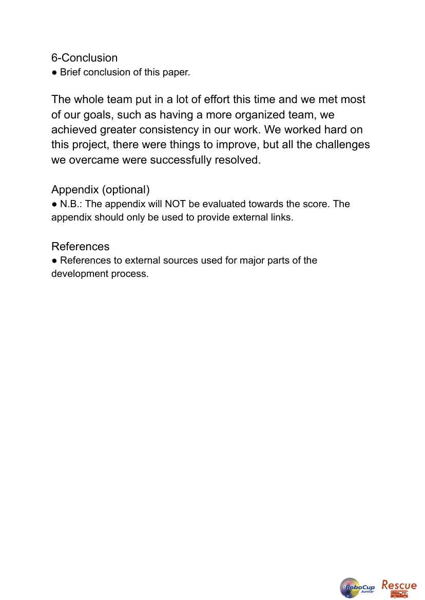
The whole team put in a lot of effort this time and we met most
of our goals, such as having a more organized team, we
achieved greater consistency in our work. We worked hard on
this project, there were things to improve, but all the challenges
we overcame were successfully resolved.
Appendix (optional)
● N.B.: The appendix will NOT be evaluated towards the score. The
appendix should only be used to provide external links.
References
● References to external sources used for major parts of the
development process.
17 pages, rendered as images so they load quickly. The text above is the document's own, extracted from the PDF.
Source code
The team's own source code, 4 KB. It is a download rather than part of this page, because a zip is something you open on your computer. It comes from GitHub, which some school networks block.