
Angora Goasbock
Document register
- Poster1 pagePublished
- Presentation videoYouTubePublished
- Bill of materials93 KBPublished
- Team description paper15 pagesPublished
- Engineering journalNot shared
- Source code1.7 MB · GitHubPublished
Sharing each document is the team's decision. “Not shared” means this team chose not to publish it, or did not submit one — not that it is missing from the archive.
In their words
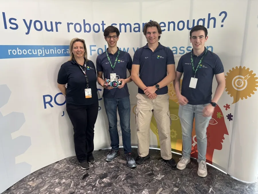
Angora Goasbock, is a RoboCupJunior Rescue Line team from HTL Zeltweg, Austria. Our team consists of three students who are responsible for programming, robot design, construction, and project management.
A fully custom robot was built around a 3D‑printed chassis and an Arduino‑based control system. The robot is required to follow a black line reliably, avoid obstacles, and autonomously identify, collect, and sort victims—represented by silver and black spheres—inside the evacuation zone.
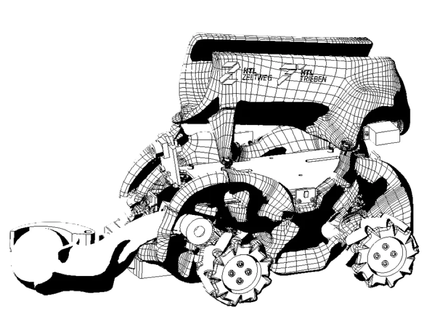
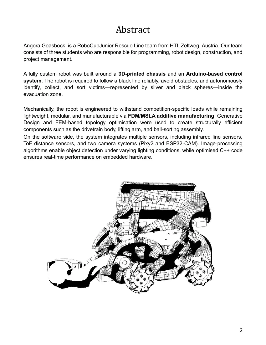
Mechanically, the robot is engineered to withstand competition‑specific loads while remaining lightweight, modular, and manufacturable via FDM/MSLA additive manufacturing. Generative Design and FEM‑based topology optimisation were used to create structurally efficient components such as the drivetrain body, lifting arm, and ball‑sorting assembly.
On the software side, the system integrates multiple sensors, including infrared line sensors, ToF distance sensors, and two camera systems (Pixy2 and ESP32‑CAM). Image‑processing algorithms enable object detection under varying lighting conditions, while optimised C++ code ensures real‑time performance on embedded hardware.
Poster
Read the text of this document — 705 words
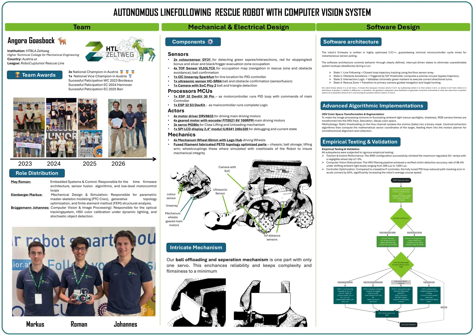
AUTONOMOUS LINEFOLLOWING RESCUE ROBOT WITH COMPUTER VISION SYSTEM
Team Mechanical & Electrical Design Software Design
Angora Goasbock Components Software architecture
Institution: HTBLA Zeltweg
Higher Technical College for Mechanical Engineering Sensors The robot's firmware is written in highly optimized C/C++, guaranteeing minimal microcontroller cycle times for
instantaneous sensor polling.
Country: Austria • 2x coloursensor GY31 for detecting green sqares/intersections, red for stopping/exit
The software architecture controls behavior through clearly defined, interrupt-driven states to eliminate unpredictable
League: RoboCupJunior Rescue Line bonus and silver and black/trigger evacuation zone occupation system lockups (deadlocks) during a run:
• 4x TOF Sensor VL53L7CX for occupation map (navigation in rescue zone and obstacle
3x National Champion in Austria avoidance); ball confirmation ➢ State 1: Line Following → Closed-loop trajectory tracking using the floor sensor array.
Team Awards 1x National Vice-Champion in Austria • 1x I2C linearray Sparkfun for line location for PID-controller ➢ State 2: Obstacle Avoidance → Triggered by ToF thresholds; computes a precise circular bypass trajectory.
➢ State 3: Intersection Logic → Validates chromatic green markers to execute correct directional turns.
Sucessful Paticipation WC 2023 Bordeaux • 1x ultrasonic sensor HC-SR04 ball and obstacle confirmation (sensorfusion) ➢ State 4: Rescue Zone → Transition to primary camera-guided navigation and target hunting.
Sucessful Paticipation EC 2024 Hannover • 1x Camera with SoC Pixy 2 ball and triangle detection
the robot knows where it is at all times. it knows this because it knows where it isn’t. by subtracting where it is from where it isn’t, or where it isn't from where it is
Sucessful Paticipation EC 2025 Bari
Processors MCUs (whichever is greater), it obtains a difference, or deviation. the guidance subsystem uses deviations to generate corrective commands to drive the robot from a position
where it is to aposition where it isn’t, and arriving at a position where it wasn't, it now is.
• 1x ESP 32 DevKit 30 Pin – as motorcontroller runs PID loop with commands of main
Controller
• 1x ESP 32 S3 DevKit - as maincontroller runs complete Logic Advanced Algorithmic Implementations
Actors HSV Color Space Transformation & Segmentation
• 4x motor driver DRV8833 for driving main driving motors To make the image processing immune to fluctuating ambient light (venue spotlights, shadows), RGB camera frames are
• 4x geared motor with encoder FIT0521 6V 100RPM main driving motors transformed into the HSV (Hue, Saturation, Value) color space.
• 3x servo MG90s for Claw Lifting and Unloading mechanism Methodology: Static thresholding on the Hue channel isolates the victims (balls) into a binary mask. Centroid extraction
algorithms then compute the mathematical vector coordinates of the target, feeding them into the motion planner for
• 1x SPI LCD display 2,4" modul ILI9341 240x320 for debugging and current state omnidirectional alignment and collection.
Mechanics
• 4x Mechanum Wheel 65mm with Lego Hub driving Wheels
• Fused filament fabricated PETG topology optimized parts – chassis; ball storage; lifting
Empirical Testing & Validation
arm; wheelcouplings these where simulated with crashloads of the Robot to insure Empirical Testing & Validation
mechanical integrity All subsystems were subjected to rigorous empirical testing:
➢ Traction & Incline Performance: The 4WD configuration successfully climbed the maximum regulated 25∘ ramps with
a negligible wheel slip of <3%.
2023 2024 2025 2026 Camera with
➢ Computer Vision Robustness: The HSV filtering pipeline achieved a verified victim detection accuracy rate of 98.4%
under shifting ambient light levels ranging from 200 Lux to 1200 Lux.
➢ Controller Optimization: Compared to a baseline P-controller, the fully tuned PID loop reduced path-tracking error in
SoC
Role Distribution acute corners by 42%, significantly increasing the robot's average course speed.
May Roman: Embedded Systems & Control: Responsible for the time firmware
architecture, sensor fusion algorithms, and low-level motorcontrol
loops Ultrasonic
Kienberger Markus: Mechanical Design & Simulation: Responsible for parametric colour Sensor
master-skeleton modeling (PTC Creo), generative topology sensor
optimization, and finite element method (FEM) structural analysis.
linearray
Brüggemann Johannes: Computer Vision & Image Processing): Responsible for the optical
trackingsystem, HSV color calibration under dynamic lighting, and Mechanum
stochastic object detection. wheels
geared main
motors
Tof distance
sensors
Intricate Mechanism
Our ball offloading and seperation mechanism is one part with only
one servo. This enchances reliability and keeps complexity and
flimsiness to a minimum
Markus Roman Johannes
1 page, rendered as images so they load quickly. The text above is the document's own, extracted from the PDF.
Presentation video
Hosted on YouTube. The player loads only when you press play.
Bill of materials
Shown as the original PDF, because this one is smaller that way and its text stays selectable and searchable.
Team description paper
Show the remaining 12 pages
Read the text of this document — 2560 words
ROBOCUPJUNIOR RESCUE (LINE) 2026
    TEAM DESCRIPTION PAPER

    Angora Goasbock 🐐

                                   1
                                        Abstract
Angora Goasbock, is a RoboCupJunior Rescue Line team from HTL Zeltweg, Austria. Our team
consists of three students who are responsible for programming, robot design, construction, and
project management.

A fully custom robot was built around a 3D-printed chassis and an Arduino-based control
system. The robot is required to follow a black line reliably, avoid obstacles, and autonomously
identify, collect, and sort victims—represented by silver and black spheres—inside the
evacuation zone.

Mechanically, the robot is engineered to withstand competition-specific loads while remaining
lightweight, modular, and manufacturable via FDM/MSLA additive manufacturing. Generative
Design and FEM-based topology optimisation were used to create structurally efficient
components such as the drivetrain body, lifting arm, and ball-sorting assembly.
On the software side, the system integrates multiple sensors, including infrared line sensors,
ToF distance sensors, and two camera systems (Pixy2 and ESP32-CAM). Image-processing
algorithms enable object detection under varying lighting conditions, while optimised C++ code
ensures real-time performance on embedded hardware.

                                                                                              2
1 Introduction
1.1 a. Team
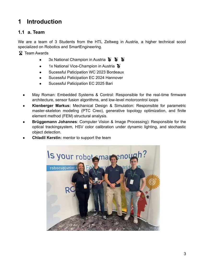
We are a team of 3 Students from the HTL Zeltweg in Austria, a higher technical scool
specialized on Robotics and SmartEngineering.
🏆 Team Awards
          ●     3x National Champion in Austria 🥇 🥇 🥇
          ●     1x National Vice-Champion in Austria 🥈
          ●     Sucessful Paticipation WC 2023 Bordeaux
          ●     Sucessful Paticipation EC 2024 Hannover
          ●     Sucessful Paticipation EC 2025 Bari

  ●    May Roman: Embedded Systems & Control: Responsible for the real-time firmware
       architecture, sensor fusion algorithms, and low-level motorcontrol loops
  ●    Kienberger Markus: Mechanical Design & Simulation: Responsible for parametric
       master-skeleton modeling (PTC Creo), generative topology optimization, and finite
       element method (FEM) structural analysis.
  ●    Brüggemann Johannes: Computer Vision & Image Processing): Responsible for the
       optical trackingsystem, HSV color calibration under dynamic lighting, and stochastic
       object detection.
  ●    Chladil Kerstin: mentor to support the team

                                                                                         3
2 Project Planning
2.1 Overall Project Plan
Our team’s objective was to design, build, program and optimize a robot that can successfully
complete competition tasks from RoboCup Junior Rescue line league, meeting all rules and
performance requirements.

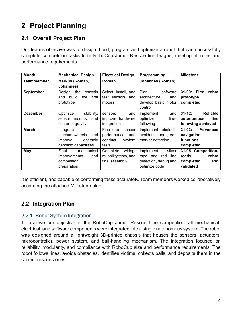
 Month            Mechanical Design            Electrical Design        Programming              Milestone
 Teammember       Markus (Roman,               Roman                    Johannes (Roman)
                  Johannes)
 September        Design the chassis           Select, install, and     Plan         software    31-09: First robot
                  and build the first          test sensors and         architecture      and    prototype
                  prototype                    motors                   develop basic motor      completed
                                                                        control
 Dezember         Optimize        stability,   sensors            and   Implement         and    31-12:      Reliable
                  sensor mounts, and           improve hardware         optimize         line-   autonomous       line
                  center of gravity            integration              following                following achieved
 March            Integrate                    Fine-tune sensor         Implement obstacle       31-03:    Advanced
                  mechanowheels and            performance and          avoidance and green      navigation
                  improve        obstacle      conduct        system    marker detection         functions
                  handling capabilities        tests                                             completed
 May              Final       mechanical       Complete wiring,         Implement      silver    31-05 Competition-
                  improvements        and      reliability tests, and   tape and red line        ready          robot
                  competition                  final assembly           detection, debug and     completed        and
                  preparation                                           optimize code            validated

It is efficient, and capable of performing tasks accurately. Team members worked collaboratively
according the attached Milestone plan.

2.2 Integration Plan

2.2.1 Robot System Integration
To achieve our objective in the RoboCup Junior Rescue Line competition, all mechanical,
electrical, and software components were integrated into a single autonomous system. The robot
was designed around a lightweight 3D-printed chassis that houses the sensors, actuators,
microcontroller, power system, and ball-handling mechanism. The integration focused on
reliability, modularity, and compliance with RoboCup size and performance requirements. The
robot follows lines, avoids obstacles, identifies victims, collects balls, and deposits them in the
correct rescue zones.

                                                                                                                     4
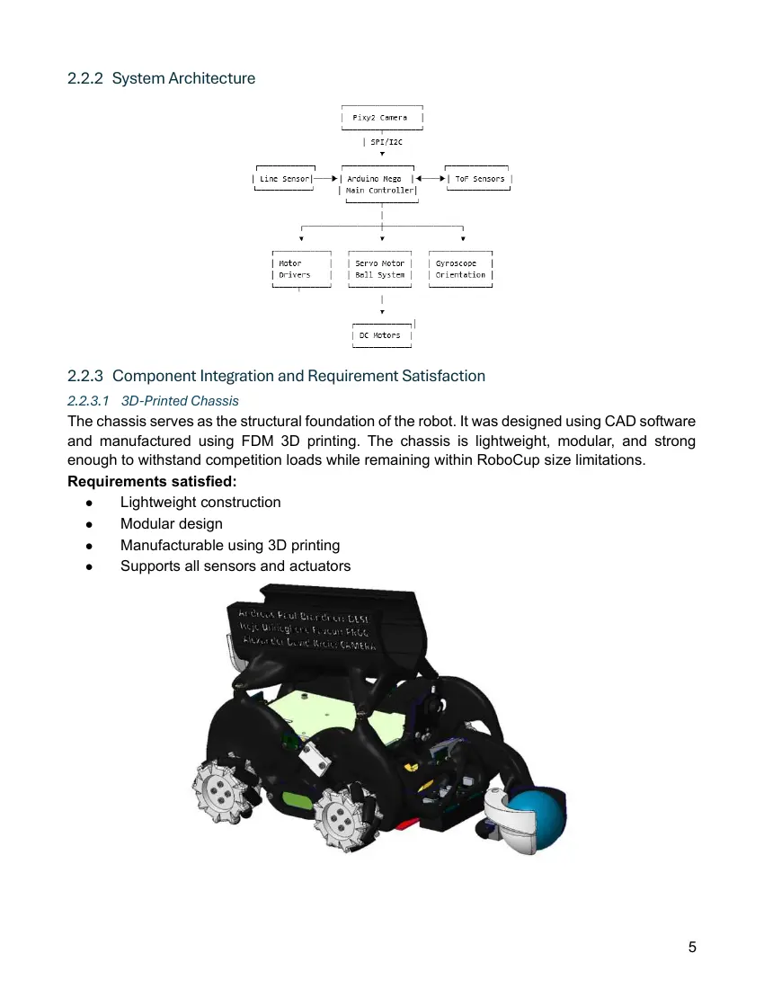
2.2.2 System Architecture

2.2.3 Component Integration and Requirement Satisfaction
2.2.3.1 3D-Printed Chassis
The chassis serves as the structural foundation of the robot. It was designed using CAD software
and manufactured using FDM 3D printing. The chassis is lightweight, modular, and strong
enough to withstand competition loads while remaining within RoboCup size limitations.
Requirements satisfied:
   ●    Lightweight construction
   ●    Modular design
   ●    Manufacturable using 3D printing
   ●    Supports all sensors and actuators

                                                                                              5
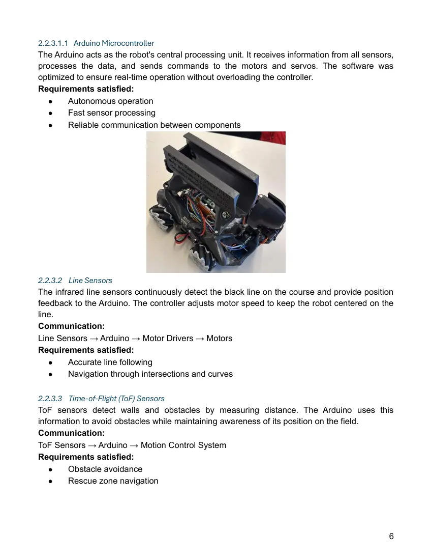
2.2.3.1.1 Arduino Microcontroller
The Arduino acts as the robot's central processing unit. It receives information from all sensors,
processes the data, and sends commands to the motors and servos. The software was
optimized to ensure real-time operation without overloading the controller.
Requirements satisfied:
   ●     Autonomous operation
   ●     Fast sensor processing
   ●     Reliable communication between components

2.2.3.2 Line Sensors
The infrared line sensors continuously detect the black line on the course and provide position
feedback to the Arduino. The controller adjusts motor speed to keep the robot centered on the
line.
Communication:
Line Sensors → Arduino → Motor Drivers → Motors
Requirements satisfied:
   ●    Accurate line following
   ●    Navigation through intersections and curves

2.2.3.3 Time-of-Flight (ToF) Sensors
ToF sensors detect walls and obstacles by measuring distance. The Arduino uses this
information to avoid obstacles while maintaining awareness of its position on the field.
Communication:
ToF Sensors → Arduino → Motion Control System
Requirements satisfied:
   ●    Obstacle avoidance
   ●    Rescue zone navigation

                                                                                                6
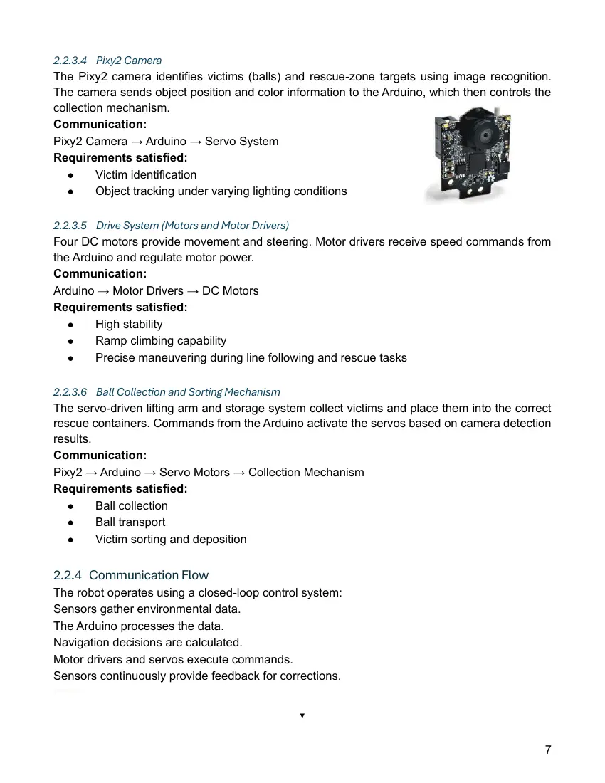
2.2.3.4 Pixy2 Camera
The Pixy2 camera identifies victims (balls) and rescue-zone targets using image recognition.
The camera sends object position and color information to the Arduino, which then controls the
collection mechanism.
Communication:
Pixy2 Camera → Arduino → Servo System
Requirements satisfied:
   ●     Victim identification
   ●     Object tracking under varying lighting conditions

2.2.3.5 Drive System (Motors and Motor Drivers)
Four DC motors provide movement and steering. Motor drivers receive speed commands from
the Arduino and regulate motor power.
Communication:
Arduino → Motor Drivers → DC Motors
Requirements satisfied:
   ●    High stability
   ●    Ramp climbing capability
   ●    Precise maneuvering during line following and rescue tasks

2.2.3.6 Ball Collection and Sorting Mechanism
The servo-driven lifting arm and storage system collect victims and place them into the correct
rescue containers. Commands from the Arduino activate the servos based on camera detection
results.
Communication:
Pixy2 → Arduino → Servo Motors → Collection Mechanism
Requirements satisfied:
   ●     Ball collection
   ●     Ball transport
   ●     Victim sorting and deposition

2.2.4 Communication Flow
The robot operates using a closed-loop control system:
Sensors gather environmental data.
The Arduino processes the data.
Navigation decisions are calculated.
Motor drivers and servos execute commands.
Sensors continuously provide feedback for corrections.
Sensors
   │
                                               ▼

                                                                                             7
                                         Arduino Controller
                                                  │
                                   ├──► Motor Drivers ─► DC Motors
                                                  │
                                 └──► Servo Motors ─► Ball Mechanism
                                                  ▲
                                                  │
                                        Feedback from Sensors

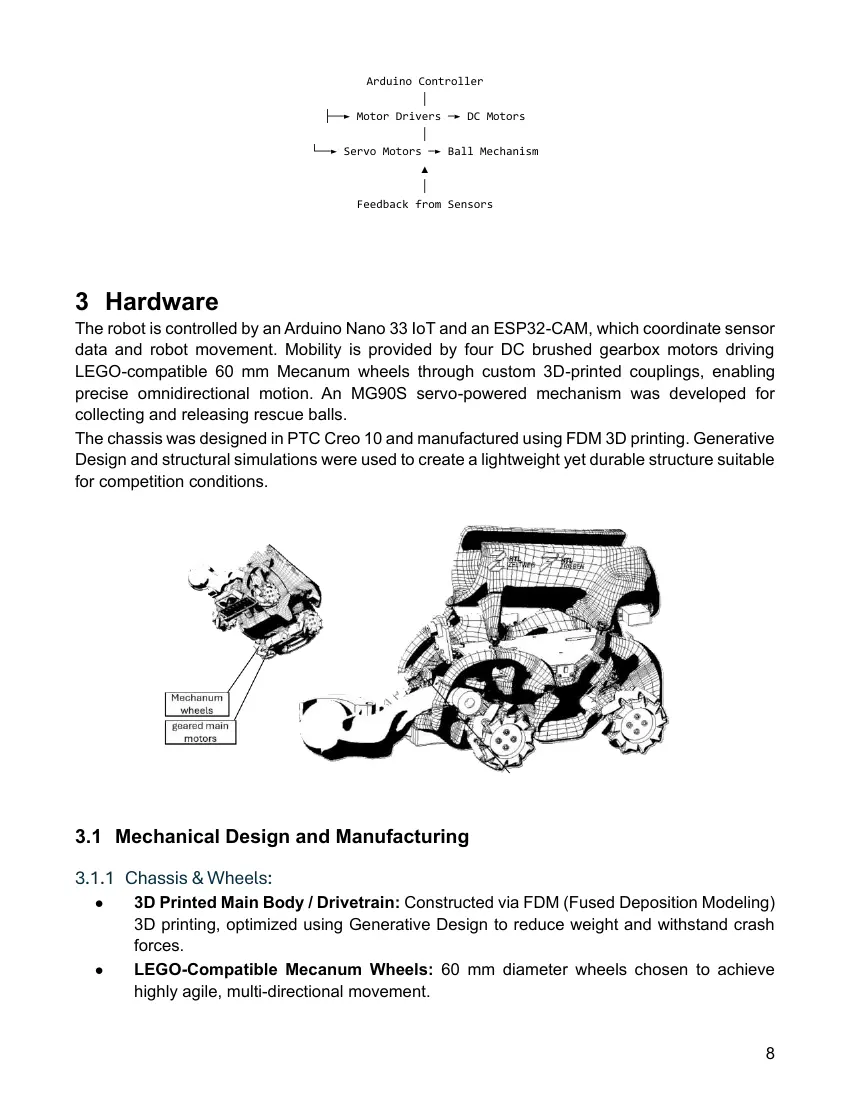
3 Hardware
The robot is controlled by an Arduino Nano 33 IoT and an ESP32-CAM, which coordinate sensor
data and robot movement. Mobility is provided by four DC brushed gearbox motors driving
LEGO-compatible 60 mm Mecanum wheels through custom 3D-printed couplings, enabling
precise omnidirectional motion. An MG90S servo-powered mechanism was developed for
collecting and releasing rescue balls.
The chassis was designed in PTC Creo 10 and manufactured using FDM 3D printing. Generative
Design and structural simulations were used to create a lightweight yet durable structure suitable
for competition conditions.

3.1 Mechanical Design and Manufacturing

3.1.1 Chassis & Wheels:
  ●     3D Printed Main Body / Drivetrain: Constructed via FDM (Fused Deposition Modeling)
        3D printing, optimized using Generative Design to reduce weight and withstand crash
        forces.
  ●     LEGO-Compatible Mecanum Wheels: 60 mm diameter wheels chosen to achieve
        highly agile, multi-directional movement.

                                                                                                8
  ●     Custom 3D-Printed Couplings: Used to interface the standard DC motor axles with
        the LEGO-compatible Mecanum wheels.
  ●     M2 & M3 Brass Metal Inserts: Integrated into the FDM plastic
        parts to handle repeated assembly and secure sensors/hardware
        tightly without stripping plastic threads.

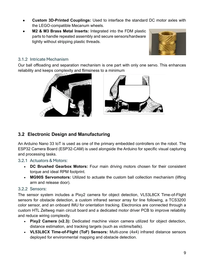
3.1.2 Intricate Mechanism
Our ball offloading and separation mechanism is one part with only one servo. This enhances
reliability and keeps complexity and flimsiness to a minimum

3.2 Electronic Design and Manufacturing
An Arduino Nano 33 IoT is used as one of the primary embedded controllers on the robot. The
ESP32 Camera Board (ESP32-CAM) is used alongside the Arduino for specific visual capturing
and processing tasks.
3.2.1 Actuators & Motors:
   •   DC Brushed Gearbox Motors: Four main driving motors chosen for their consistent
       torque and ideal RPM footprint.
   •   MG90S Servomotors: Utilized to actuate the custom ball collection mechanism (lifting
       arm and release door).
3.2.2 Sensors:
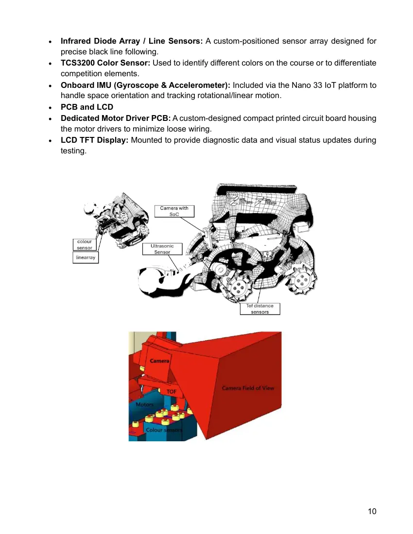
The sensor system includes a Pixy2 camera for object detection, VL53L8CX Time-of-Flight
sensors for obstacle detection, a custom infrared sensor array for line following, a TCS3200
color sensor, and an onboard IMU for orientation tracking. Electronics are connected through a
custom HTL Zeltweg main circuit board and a dedicated motor driver PCB to improve reliability
and reduce wiring complexity.
   • Pixy2 Camera (v2.3): Dedicated machine vision camera utilized for object detection,
       distance estimation, and tracking targets (such as victims/balls).
   • VL53L8CX Time-of-Flight (ToF) Sensors: Multi-zone (4x4) infrared distance sensors
       deployed for environmental mapping and obstacle detection.

                                                                                            9
•   Infrared Diode Array / Line Sensors: A custom-positioned sensor array designed for
    precise black line following.
•   TCS3200 Color Sensor: Used to identify different colors on the course or to differentiate
    competition elements.
•   Onboard IMU (Gyroscope & Accelerometer): Included via the Nano 33 IoT platform to
    handle space orientation and tracking rotational/linear motion.
•   PCB and LCD
•   Dedicated Motor Driver PCB: A custom-designed compact printed circuit board housing
    the motor drivers to minimize loose wiring.
•   LCD TFT Display: Mounted to provide diagnostic data and visual status updates during
    testing.

                                                                                          10
4 Software

4.1 Software Overview

4.1.1 Development Environments (IDEs):
   •   Visual Studio Code (VS Code): Used as the primary source code editor.
   •   PlatformIO IDE: An extension implemented within VS Code to manage Arduino libraries,
       compile codes, and handle micro-controller flashing.
   •   Arduino IDE: Used for general firmware debugging, board management, and library
       tracking.
4.1.2 Programming Languages:
   •   C / C++: The primary programming languages utilized to write optimized code directly for
       the microcontrollers and their attached sensors.
   •   Key Software Frameworks & External Libraries:
   •   Arduino Core Library (Arduino.h): The baseline framework for managing pin
       configurations and standard tasks.
   •   Pixy2 Library: Utilized for camera initialization, signature tracking, and retrieving spatial
       parameters from detected objects.
   •   VL53L8CX / ToF API Libraries: Employed to coordinate multi-zone I²C addresses and
       safely grab distance matrix frames.
4.1.3 CAD & Simulation Engineering Software:
   •   PTC Creo 10: The main Computer-Aided Design (CAD) environment used for skeletal
       modeling and defining the boundaries of the robot assembly.
   •   Creo Generative Design Extension / Simulation Solver: Utilized for finite element
       method (FEM) loading calculations and topology optimization to algorithmically shape the
       chassis components for weight savings.

4.2 Software architecture
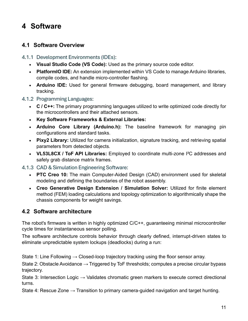
The robot's firmware is written in highly optimized C/C++, guaranteeing minimal microcontroller
cycle times for instantaneous sensor polling.
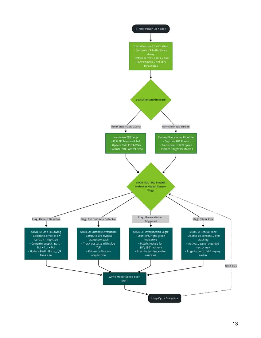
The software architecture controls behavior through clearly defined, interrupt-driven states to
eliminate unpredictable system lockups (deadlocks) during a run:

State 1: Line Following → Closed-loop trajectory tracking using the floor sensor array.
State 2: Obstacle Avoidance → Triggered by ToF thresholds; computes a precise circular bypass
trajectory.
State 3: Intersection Logic → Validates chromatic green markers to execute correct directional
turns.
State 4: Rescue Zone → Transition to primary camera-guided navigation and target hunting.

                                                                                                 11
the robot knows where it is at all times.it knows this because it knows where it isn’t. by subtracting
where it is from where it isn’t, or where it isn't from where it is (whichever is greater), it obtains a
difference, or deviation. the guidance subsystem uses deviations to generate corrective
commands to drive the robot from a position where it is to aposition where it isn’t, and arriving
at a position where it wasn't, it now is.

4.2.1 Advanced Algorithmic Implementations
HSV Color Space Transformation & Segmentation
To make the image processing immune to fluctuating ambient light (venue spotlights, shadows),
RGB camera frames are transformed into the HSV (Hue, Saturation, Value) color space.
Methodology: Static thresholding on the Hue channel isolates the victims (balls) into a binary
mask. Centroid extraction algorithms then compute the mathematical vector coordinates of the
target, feeding them into the motion planner for omnidirectional alignment and collection.

                                                                                                     12
13
4.3 Innovative solutions

The robot incorporates several innovative hardware and engineering solutions that were
specifically developed to improve performance, reliability, and manufacturability in the
RoboCup Junior Rescue competition. Rather than relying on standard robotics kits, the
entire platform was designed as a custom system optimized for rescue tasks such as line
following, obstacle avoidance, victim detection, and ball collection.

●   One of the most significant innovations is the use of a generatively designed 3D-printed
    chassis. The robot structure was created using PTC Creo Generative Design and finite
    element analysis (FEA) tools to automatically optimize material distribution. This process
    reduced the overall weight while maintaining the structural strength required to survive
    collisions, ramps, and repeated competition use. The resulting design achieved a lightweight
    yet rigid frame that could not easily be produced through conventional design methods.
●   Another innovative feature is the combination of LEGO-compatible Mecanum wheels with
    custom-designed 3D-printed motor couplings. Standard Mecanum wheels are typically not
    compatible with the selected gearbox motors. To solve this challenge, custom couplings
    were engineered and manufactured using FDM 3D printing. This solution enabled
    omnidirectional movement while maintaining the advantages of the chosen drive system,
    giving the robot exceptional maneuverability in confined rescue areas.
●   The robot also features a fully custom ball collection mechanism designed specifically for
    Rescue Line challenges. Instead of using commercially available grippers, a lightweight
    servo-actuated lifting arm and release system was developed. This mechanism allows
    victims to be collected quickly and deposited accurately into rescue zones while minimizing
    mechanical complexity and weight.
●   From an electronics perspective, the robot uses a custom PCB architecture consisting of a
    dedicated main circuit board and a separate motor-driver board. This significantly reduces
    cable clutter, improves reliability, simplifies maintenance, and allows rapid replacement of
    individual modules.
●   The integration of brass threaded inserts directly into the 3D-printed parts further improves
    durability by preventing thread wear during repeated assembly and testing.
●   The sensor system combines multiple technologies to create a robust perception platform.
    A Pixy2 vision camera, VL53L8CX multi-zone Time-of-Flight sensors, infrared line sensors,
    color sensors, and an onboard IMU work together to provide environmental awareness. This
    sensor fusion approach increases reliability compared to single-sensor solutions and
    allows the robot to adapt to changing competition conditions.
•   Finally, the project demonstrates innovation through the close integration of
    advanced CAD design, additive manufacturing, custom electronics, and embedded
    systems engineering. The combination of optimized mechanical structures, custom
    hardware, and intelligent sensor integration results in a highly efficient and
    competition-ready rescue robot that balances performance, reliability, and
    manufacturability.

                                                                                              14
5 Performance evaluation
All subsystems were subjected to rigorous empirical testing:
Traction & Incline Performance: The 4WD configuration successfully climbed the maximum
regulated 25∘ ramps with a negligible wheel slip of <3%.
Computer Vision Robustness: The HSV filtering pipeline achieved a verified victim detection
accuracy rate of 98.4% under shifting ambient light levels ranging from 200 Lux to 1200 Lux.
Controller Optimization: Compared to a baseline P-controller, the fully tuned PID loop reduced
path-tracking error in acute corners by 42%, significantly increasing the robot's average course
speed.
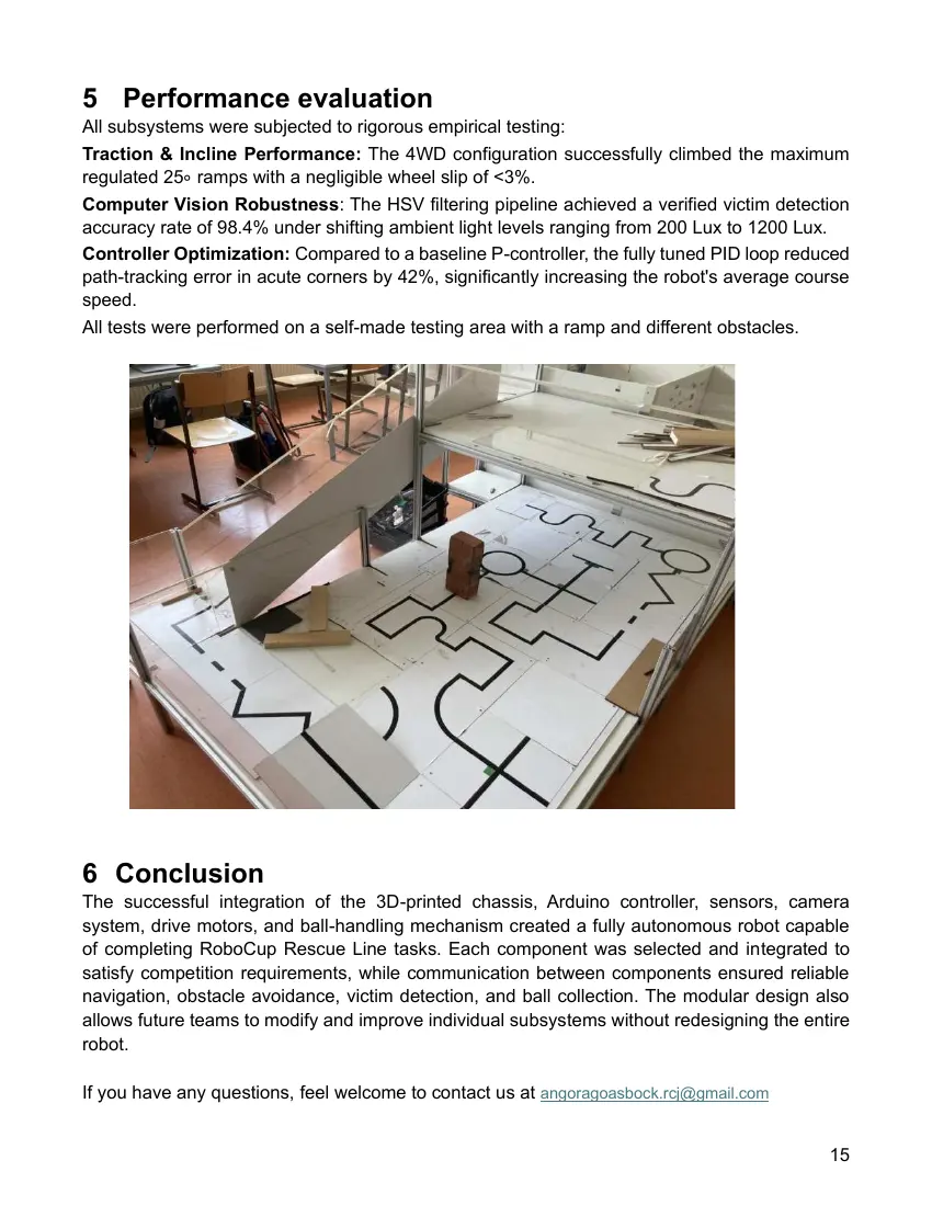
All tests were performed on a self-made testing area with a ramp and different obstacles.

6 Conclusion
The successful integration of the 3D-printed chassis, Arduino controller, sensors, camera
system, drive motors, and ball-handling mechanism created a fully autonomous robot capable
of completing RoboCup Rescue Line tasks. Each component was selected and integrated to
satisfy competition requirements, while communication between components ensured reliable
navigation, obstacle avoidance, victim detection, and ball collection. The modular design also
allows future teams to modify and improve individual subsystems without redesigning the entire
robot.

If you have any questions, feel welcome to contact us at angoragoasbock.rcj@gmail.com

                                                                                             15
15 pages, rendered as images so they load quickly. The text above is the document's own, extracted from the PDF.
Source code
The team's own source code, 1.7 MB. It is a download rather than part of this page, because a zip is something you open on your computer. It comes from GitHub, which some school networks block.